A Guide to Fire Pumps on Ship
Fire pumps are among the most critical pieces of safety equipment on any vessel. In a fire emergency at sea, they are the primary means of delivering water to hoses and fixed suppression systems across the ship. Without an operational fire pump, a fire that could have been contained becomes uncontrollable within minutes. Understanding how fire pumps are classified, what regulations govern them, how they are operated, and how they must be maintained is essential knowledge for every engineer and deck officer.
Types of Fire Pumps on Ships
Ships carry two distinct categories of fire pump: main fire pumps and the emergency fire pump. Each serves a specific role and is subject to separate regulatory requirements under SOLAS (Safety of Life at Sea).
Main Fire Pumps
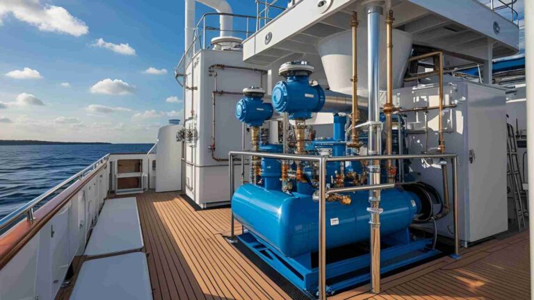
Main fire pumps are located inside the ship’s engine room, typically on the bottom platform near the general service pumps and ballast pumps. They draw seawater through a dedicated sea suction and deliver it into the ship’s fire main — the pressurised piping network that runs throughout the vessel and feeds every hydrant connection on board.
Centrifugal pumps are the standard choice for main fire pumps because of their high flow capability and ability to handle water at varying pressures. Where centrifugal pumps are used, non-return valves must be fitted on the discharge side to prevent backflow when the pump is not running. Where positive displacement pumps are used instead, a relief valve is mandatory to prevent over-pressurisation if the discharge valve is closed while the pump is running.
Main fire pumps supply water to a wide range of systems beyond fire hoses, including anchor washing at the forecastle, ejectors in cargo hold bilges and dangerous cargo hold bilges, and swimming pools on passenger vessels where fitted. General service pump lines are often interconnected with the fire main, allowing the general service pump to supply the fire system when needed — these are sometimes called general service and fire pumps. They must never be used for pumping oil under any circumstances.
The Emergency Fire Pump
The emergency fire pump exists specifically because a fire in the engine room — the most common location for serious fires — could render all main fire pumps inoperable simultaneously. A blackout, fire damage, or explosion could cut off electrical supply, flood the engine room with smoke, or physically destroy the pump. The emergency fire pump is positioned to remain functional even in these worst-case scenarios.
Its defining characteristic is its physical and electrical separation from the main machinery space. It must be located in a compartment that does not form part of the engine room, with its own independent power source, its own sea suction, and starting controls that do not rely on the main switchboard or any infrastructure inside the engine room.
SOLAS Requirements: Pump Numbers and Capacity
The number and capacity of fire pumps required on a ship depends on the vessel type and gross tonnage. The following table summarises the key SOLAS requirements:
| Ship Type | Gross Tonnage | Minimum Main Fire Pumps | Notes |
|---|---|---|---|
| Passenger ship | Under 4,000 GT | 2 independent pumps | — |
| Passenger ship | 4,000 GT and above | 3 independent pumps | — |
| Cargo ship | Over 1,000 GT | 2 pumps with independent drives | — |
| Cargo ship | Under 1,000 GT | As determined by the administration | — |
For cargo ships, each individual main fire pump must have a capacity of not less than 80% of the total required output divided by the minimum number of required pumps, and in no case less than 25 m³/hr. The total combined capacity of the main fire pumps in a cargo ship need not exceed 180 m³/hr.
For passenger ships, the combined output of main fire pumps must be capable of delivering not less than two-thirds of the capacity provided by the bilge pumps. For cargo ships, this benchmark is set at four-thirds of the equivalent bilge pump output for a passenger ship of similar dimensions.
Emergency Fire Pump Requirements
| Requirement | Specification |
|---|---|
| Applicable vessels | Passenger ships ≥1,000 GT; cargo ships ≥2,000 GT |
| Location | Outside the engine room, in a separate compartment |
| Power source | Diesel engine (self-cooled compression ignition) or electric motor from emergency generator |
| Minimum capacity | 25 m³/hr |
| Delivery | Two ½-inch bore jets with horizontal throw not less than 40 ft (approx. 12 m) |
| Maximum suction head | 4.5 m under all conditions of list and trim |
| Diesel fuel tank capacity | Sufficient for 3 hours at full load |
| Reserve fuel | Separate tank outside machinery space |
| Starting capability | Must achieve at least 6 starts in 30 minutes; at least 2 starts in first 10 minutes |
| Priming | Self-priming type required if located above waterline |
| Starting method | Manual, battery, hydraulic, or compressed air — operable by one person |
If the emergency pump room is only accessible through an adjacent machinery space, an A-60 class fire-resistant boundary must separate the two spaces. Electrical cables serving the emergency pump must not pass through the main machinery space unless they are of fire-resistant type and specially protected.
The preferred locations for emergency fire pumps include the steering gear flat, the shaft tunnel, the bow thruster room, or an upper deck installation with direct deck access. The specific location on each vessel is subject to classification society approval.
Fire Main System: Pipework, Hydrants, and Hoses
The fire main is the backbone of the ship’s firefighting water supply. It is defined as starting at the fire pump discharge valve and extending through all branches to every hydrant on the vessel.
Pipework
Fire main pipework is typically galvanised steel to resist the corrosion effects of seawater. Pipe bore diameters range from 50 mm to 180 mm depending on vessel size and type. The internal bore of hydrant standpipes and hydrant valves made of galvanised steel should not generally be less than 64 mm; copper alloy standpipes may be accepted at a minimum bore of 50 mm.
Welding or hot-cutting directly on fire main pipework must be avoided — it damages the galvanised coating and compromises corrosion resistance. Any significant repair requires replacement of the affected section with new galvanised pipe.
All fire main materials must remain effective under high heat. Fittings are accepted if made of materials with a melting point above 1,000°C, or if they have passed a standard fire test at 800°C for 10 minutes. Where working pressure at pump discharge exceeds 7 bar, the fire main must be hydrostatically tested to 2.0 times maximum working pressure; where below 7 bar, testing to 1.5 times is required.
The deck fire main must have isolation valves outside the machinery space so that it can be separated from the engine room section during a fire, while still allowing the emergency fire pump to supply the machinery space hydrants through a separate route.
Hydrants
Hydrants must be positioned so that every part of the ship can be reached by at least two jets of water from different hose connections. At least one hydrant with hose, nozzle, and coupling wrench must be provided in each category A machinery space.
Where hydrant blank caps are fitted, they should be designed to safely release accumulated air or vapour pressure before the cap is fully removed — this prevents sudden pressure release injuring crew during an emergency.
Hoses and Nozzles
Standard fire hoses on ships with power pumps are 64 mm diameter unlined canvas; lined hoses of 45 mm bore are widely accepted and preferred in confined spaces such as machinery rooms because they are more easily handled.
Hose length requirements under SOLAS are as follows:
| Location | Minimum Length | Maximum Length |
|---|---|---|
| Machinery spaces | 10 m | 15 m |
| Other internal spaces | 10 m | 20 m |
| Open decks (ship breadth ≤30 m) | 10 m | 20 m |
| Open decks (ship breadth >30 m) | 10 m | 25 m |
In passenger ship interiors, fire hoses must remain connected to hydrants at all times.
Standard nozzle sizes are 12 mm, 16 mm, and 19 mm. The approximate flow rates through these nozzles at common pressures are:
| Pressure (N/mm²) | 12 mm nozzle (m³/hr) | 16 mm nozzle (m³/hr) | 19 mm nozzle (m³/hr) |
|---|---|---|---|
| 0.21 | 9 | 14 | 20.5 |
| 0.25 | 10 | 15 | 22.5 |
| 0.27 | 10.5 | 16 | 23.5 |
| 0.31 | 11 | 17 | 25 |
| 0.40 | 12 | 20 | 30 |
Dual-purpose nozzles capable of both plain jet and spray settings are widely used. The spray setting should produce a fine mist that forms a protective curtain with a cone diameter of approximately 5 m at 2 m from the nozzle tip, allowing crew to approach a fire while protected.
Hose pressure at any hydrant should not exceed the level at which one person can safely control the jet. Where hydrant pressure exceeds 7 bar, this must be demonstrated to the surveyor’s satisfaction.
Remote Operation and Control Locations
In addition to local operation from the pump itself, fire pumps can be started and controlled remotely from several positions on the vessel:
- Fire control station
- Engine control room
- Bridge
- Forecastle (where this arrangement is provided)
Starting instructions must be clearly posted at each emergency fire pump location. Emergency pump starting controls must be situated outside the main machinery space and be accessible under all weather conditions.
Starting Procedure for the Main Fire Pump
The correct sequence for starting a centrifugal fire pump from its local position is:
- Verify the sea suction valve is fully open
- If the pump is of self-priming type with a vacuum pump, confirm the priming water supply tank is full
- Close the discharge valve and open the air vent on the volute casing
- Wait until water flows from the vent, then close it
- Start the pump motor
- Gradually open the discharge valve
- For self-priming centrifugal pumps, close the check valve on the vacuum pump line once the main pump is running
Monitor suction and discharge pressure gauges to confirm the pump is delivering water at the correct pressure. If pressure is not established within a few seconds of opening the discharge valve, stop the pump and investigate before attempting a restart.
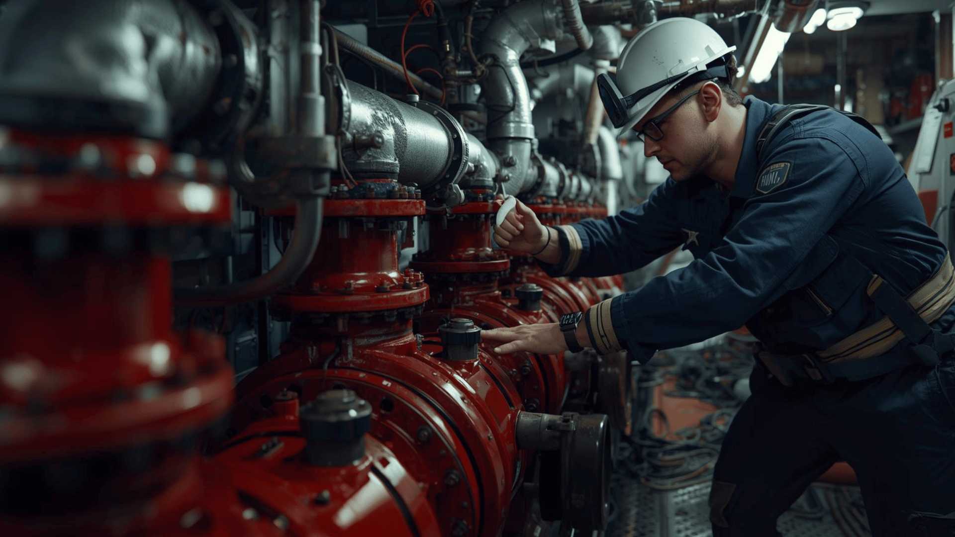
Maintenance and Inspection Checklist
Fire pumps must be tested regularly — during weekly routines, fire drills, and prior to any period of layup or dry docking. Records of all tests must be maintained in the ship’s record books.
Routine Maintenance Checks
| Check Item | Action Required |
|---|---|
| Bearings | Lubricate with correct oil or grease at specified intervals |
| Bearing temperature | Check during operation — elevated temperature indicates lubrication failure or misalignment |
| Gland packing | Minor water drip is acceptable; excessive leakage requires repacking |
| Mechanical seal | Zero leakage is the standard — any visible leakage requires seal inspection |
| Non-return valves | Check standby pump — if it rotates when the duty pump is running, the non-return valve is passing |
| Noise and vibration | Investigate any abnormal sounds immediately |
| Emergency pump fuel tank | Keep diesel tank above three-quarters full at all times |
| Emergency pump batteries | Verify trickle charge function and confirm batteries can deliver minimum 6 cold starts |
| Emergency pump room temperature | Ensure space is ventilated and heating units (where fitted) are functional |
Pre-Layup and Cold Weather Precautions
When a fire pump will be out of service for an extended period — during dry dock, layup, or scheduled downtime — close both suction and discharge valves to prevent seawater ingress through degraded non-return valves. In cold weather or freezing conditions, drain the fire main and deck wash lines completely to prevent frost damage to pipework and pump casings.
When operating in the bow thruster room to start a diesel-driven emergency pump during a blackout condition, always prop the room door open before entering. Without main power, the space ventilation fan will not run, and there is a risk of oxygen depletion or exhaust gas accumulation while the diesel engine is running.
Inspection at Survey
During initial and re-surveys, the following items are verified by the surveyor:
For the fire main — correct materials, approved joint types, successful pressure tests, accessible non-return valves, operational isolation valves, and satisfactory insulated sections within machinery spaces.
For fire pumps — confirmed remote and automatic start capability, efficient pump operation, adequate priming systems, and correct hydrant pressures delivered at the highest hydrant on the ship.
For the emergency fire pump — verified physical separation from main pumps, independent power supply routes, satisfactory heating arrangements, tested starting systems capable of six starts in thirty minutes, and adequate fuel supply both immediate and in reserve.
A ship’s fire pump system is only as reliable as the maintenance and testing record behind it. The regulations exist because the cost of failure is measured not in money but in lives. Keeping fire pumps operationally ready at all times is one of the most fundamental responsibilities in ship safety management.
Happy Boating!
Share A Guide to Fire Pumps on Ship with your friends and leave a comment below with your thoughts.
Read What To Do When Black Smoke Is Coming Out Of Ship’s Funnel At Port? until we meet in the next article.