7 Technologies To Reduce Fuel Consumption Of Ships
Fuel is the single largest operating cost for most vessel types, typically accounting for 50–60% of total voyage expenses. For a VLCC or large containership burning several hundred tonnes of heavy fuel oil per day, even a 5% efficiency improvement translates to millions of dollars in annual savings — and a measurable reduction in greenhouse gas emissions. With IMO’s Carbon Intensity Indicator (CII) and Energy Efficiency Existing Ship Index (EEXI) regulations now in force, fuel efficiency has moved from a commercial priority to a regulatory requirement.
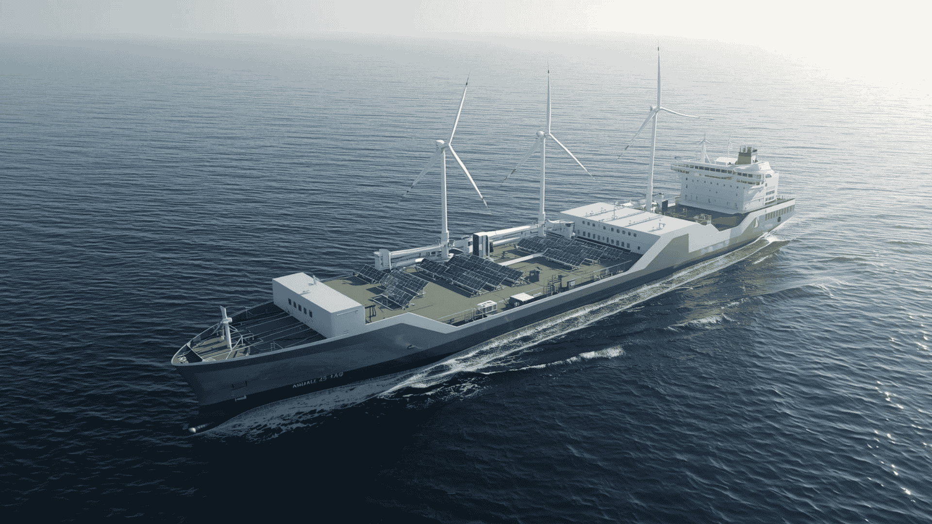
The technologies covered here span hull design, propulsion, onboard power management, combustion chemistry, and renewable energy. Some are mature and widely deployed; others are proving themselves in commercial trials. All of them address the same underlying physics: a ship consumes fuel to overcome resistance and generate propulsion, so every improvement either reduces resistance, improves propulsion efficiency, or recovers energy that would otherwise be lost.
The Regulatory Context
IMO’s strategy targets net-zero greenhouse gas emissions from shipping by or around 2050. The EEXI sets a minimum technical efficiency standard for existing ships, while the CII rates operational carbon intensity annually on a scale from A to E. Ships rated D or E for three consecutive years face mandatory corrective action plans. These regulations mean that fuel-saving investments are no longer optional for commercially active vessels — they are the mechanism by which operators maintain their ability to trade.
Technology Overview
1. Air Lubrication Systems
Air lubrication — sometimes called “bubble technology” — reduces frictional resistance between the hull and seawater by injecting a continuous layer of microbubbles along the underside of the vessel. Friction drag accounts for a substantial portion of total resistance, particularly for large, flat-bottomed vessels like tankers, bulk carriers, and cruise ships. Reducing that friction directly reduces the power required to maintain a given speed.
The system works by pumping compressed air through nozzles or slots in the hull bottom, creating an air carpet between the steel and the water. Silverstream Technologies’ Silverstream System — installed commercially on a Norwegian Cruise Line vessel — produces this microbubble layer across the full hull breadth. It can be incorporated into a newbuild design or retrofitted during approximately 14 days of drydock time.
| Parameter | Specification |
|---|---|
| CO2 reduction potential | 10–15% |
| Best suited vessel types | Tankers, bulk carriers, cruise ships, RoPax |
| Installation method | Newbuild or retrofit |
| Retrofit drydock time | ~14 days |
| Primary mechanism | Frictional resistance reduction |
Efficiency gains depend on hull form, operating speed, and draught. Vessels with large flat bottom areas operating at consistent speeds see the greatest benefit.
2. Fuel-Saving Propeller Attachments
The propeller hub generates a hub vortex — a region of turbulent, rotating water behind the blade root that represents wasted propulsive energy. Propeller Boss Cap Fins (PBCF) and devices such as the Hyundai Heavy Industries (HHI) Hi-FIN counter this vortex by generating opposing swirls, recovering energy that would otherwise dissipate in the wake and improving overall propulsion efficiency.
In a year-long trial aboard a 162,000 m³ LNG carrier, Hi-FIN demonstrated 2.5% fuel savings compared to an equivalent vessel without the device. Applied to an 8,600 TEU containership, the same saving translates to approximately $750,000 per year — or $19 million over the vessel’s 25-year lifetime. The device has since been qualified for VLCCs, LPG carriers, and containerships.
| Parameter | Specification |
|---|---|
| Fuel saving range | Up to 5% (PBCF); 2.5% demonstrated (Hi-FIN) |
| Trial vessel | 162,000 m³ LNG carrier |
| Annual saving (8,600 TEU containership) | ~$750,000/year |
| Lifetime saving estimate | ~$19 million (25 years) |
| Mechanism | Counter-vortex generation at propeller hub |
| Compatible vessel types | LNG carriers, VLCCs, LPG carriers, containerships |
These are passive devices with no moving parts or power consumption, making them low-maintenance and installable during routine drydocking.
3. Onboard DC Grid Systems
Traditional ship power systems use alternating current (AC) distribution, requiring generators to run at fixed speeds to maintain grid frequency. This forces engines to operate outside their optimal efficiency range when power demand is partial — a common condition for offshore vessels, ferries, and cruise ships with variable loads.
ABB’s Onboard DC Grid replaces the AC bus with a direct current distribution architecture. Because DC does not require frequency synchronisation, engines run at variable speeds — always at the rpm that delivers best fuel efficiency for actual power demand. Trials conducted by Pon Power and ABB aboard the platform supply vessel Dina Star measured a specific fuel oil consumption (SFOC) reduction of up to 27%. The same trials recorded a 30% reduction in engine room noise.
| Parameter | Specification |
|---|---|
| SFOC reduction | Up to 27% |
| Engine room noise reduction | 30% |
| Test vessel | PSV Dina Star (Myklebusthaug Offshore) |
| Key mechanism | Variable-speed engine operation via DC distribution |
| Best suited vessel types | Offshore vessels, ferries, cruise ships |
4. Low Loss Hybrid Energy Systems
Wärtsilä’s Low Loss Hybrid (LLH) system combines multiple power sources with energy storage — typically battery banks — to smooth transient load variations and keep prime movers operating at or near their optimal design point continuously.
In conventional power plants, transient load spikes from thruster activation, crane operation, or rapid manoeuvring force engines to accelerate rapidly, briefly operating in high-consumption, high-emission regions of their performance curves. The LLH system absorbs these spikes through energy storage that responds within milliseconds — far faster than any diesel generator. Generators then operate at stable, optimal loads.
The system integrates with existing power management systems via inverter control units, making it compatible with a wide range of vessel types and plant configurations.
| Parameter | Specification |
|---|---|
| Annual fuel saving | Up to 15% (configuration-dependent) |
| Response mechanism | Battery storage absorbs transient loads |
| Integration | Compatible with conventional PMS |
| Additional benefit | Increased power redundancy; reduced maintenance |
| Best suited vessel types | Offshore, cruise, ferries, cable layers |
The increased power redundancy also improves reliability — energy storage provides instant backup if a generator trips during transient loading, substantially reducing blackout risk.
5. Bulbous Bow Modification
The bulbous bow generates a wave that partially cancels the ship’s bow wave, reducing wave-making resistance. However, the optimal bulb geometry is highly speed- and draught-specific. A bulb designed for a vessel’s original service profile may perform poorly — or even increase resistance — when the vessel operates at different speeds due to slow steaming or changed cargo profiles.
Modifying or replacing the bulbous bow to match the vessel’s actual operating profile is one of the most proven fuel-saving interventions available. Work is done during drydocking and is permanent, requiring no ongoing maintenance or operational change.
| Operator / Study | Fuel or Emission Saving | Vessel Type |
|---|---|---|
| NYK Group | 23% CO2 reduction (verified, 6 months) | Containership |
| Maersk Group | ~8% fuel cost reduction | Container vessel (slow steaming) |
| DNV comprehensive study | ~1,000 tonnes/year fuel saving | Large merchant vessel |
| Clipper Group | Significant savings (reported) | Bulk carrier |
The investment case is strongest where the gap between the bow’s original design speed and current operating speed is greatest — common across vessels that have significantly reduced speed since delivery as fuel prices increased.
6. Fuel Oil Emulsion Technology
Fuel Oil Emulsion (FOE) technology introduces a controlled proportion of water into the fuel oil before combustion. Rather than diluting the fuel, the emulsification process creates a stable mixture in which microscopic water droplets are dispersed throughout the fuel. During combustion, these droplets vaporise explosively — a phenomenon called micro-explosion — breaking fuel droplets into finer particles, improving atomisation, and producing more complete combustion.
The consequences are measurable: less unburnt fuel per power output unit, lower peak combustion temperatures that reduce NOx formation, and less soot and particulate formation. Lower temperatures also reduce thermal stress on combustion components, with potential benefits for maintenance intervals.
Blended Fuel Solutions’ FOE technology demonstrated these outcomes in commercial trials. FOE requires onboard emulsification equipment but involves no modification to the engine itself.
| Parameter | Outcome |
|---|---|
| Combustion completeness | Improved via micro-explosion effect |
| Fuel consumption | Reduced |
| NOx emissions | Reduced (lower peak temperatures) |
| Engine operating temperature | Lower |
| Maintenance implication | Potential reduction in combustion-side servicing frequency |
7. Wind and Solar Power
Wind-assisted propulsion has returned to commercial shipping as a proven fuel-saving technology — not as traditional canvas sails, but as automated, aerodynamically optimised systems that provide supplementary thrust while the main engine handles the remainder.
Rotor Sails (Flettner Rotors)
Rotor sails use the Magnus effect: a spinning cylinder in a crosswind generates lift perpendicular to the wind, translating into forward thrust when the rotor is oriented correctly. The system is fully automated, with sensors monitoring wind conditions continuously and rotors adjusting their spin to maximise thrust contribution.
Norsepower’s commercial sea trials confirmed fuel savings of 2.6% from a single small rotor sail. A Deltamarin ro-pax design featuring six rotor sails projects proportionally higher savings. Across documented installations, rotor sails reduce main engine load by 5–20% depending on route, vessel type, and prevailing wind conditions.
Fixed Wing Sail Systems
Windship Technology’s Auxiliary Sail Propulsion System (ASPS) uses fixed aerodynamic wing technology. Two 35-metre masts, each carrying three aerodynamic wings, rotate automatically to optimise the angle of attack to prevailing wind. As wind speed and direction vary, the system modulates power output, allowing corresponding engine power reductions to maintain vessel speed.
Solar Power
Solar power aboard ships primarily offsets auxiliary electrical load — hotel systems, navigation, lighting, and pumps — reducing demand on auxiliary generators rather than contributing directly to propulsion. Eco Marine Power has completed commercial trials of shipboard solar arrays and moved them to commercial availability.
| Technology | Fuel Saving Range | Mechanism |
|---|---|---|
| Rotor sails (single unit) | 2.6%+ | Magnus effect thrust |
| Rotor sails (multiple units) | 5–20% engine load reduction | Magnus effect thrust |
| Fixed wing sails (ASPS) | Route-dependent | Aerodynamic lift |
| Solar panels | Auxiliary load offset | PV electricity generation |
Wind-assisted propulsion performs best on routes with consistent beam or quartering winds — North Atlantic and trans-Pacific lanes are particularly favourable.
Additional Fuel-Saving Strategies
Beyond the seven primary technologies, complementary measures contribute meaningfully to fuel reduction and regulatory compliance:
| Strategy | Fuel Saving Potential | Notes |
|---|---|---|
| Slow steaming / speed optimisation | 20–30% per 10% speed reduction | Most immediately accessible lever |
| Advanced anti-fouling hull coatings | 3–8% | Self-polishing and foul-release coatings |
| Regular underwater hull cleaning | 2–10% | Biofouling drag increases progressively |
| Waste heat recovery systems | 5–10% | Exhaust heat converted to steam or electricity |
| Bow air deflectors | 1–3% | Aerodynamic drag reduction on superstructure |
| LNG or alternative fuel transition | 20–25% CO2 reduction vs HFO | Infrastructure and procurement considerations |
| Voyage optimisation software | 3–8% | Weather routing, trim and speed optimisation |
Selecting and Stacking Technologies
No single technology suits every vessel. Selection depends on vessel type, trade route, age, operating profile, and the current CII rating gap to be closed.
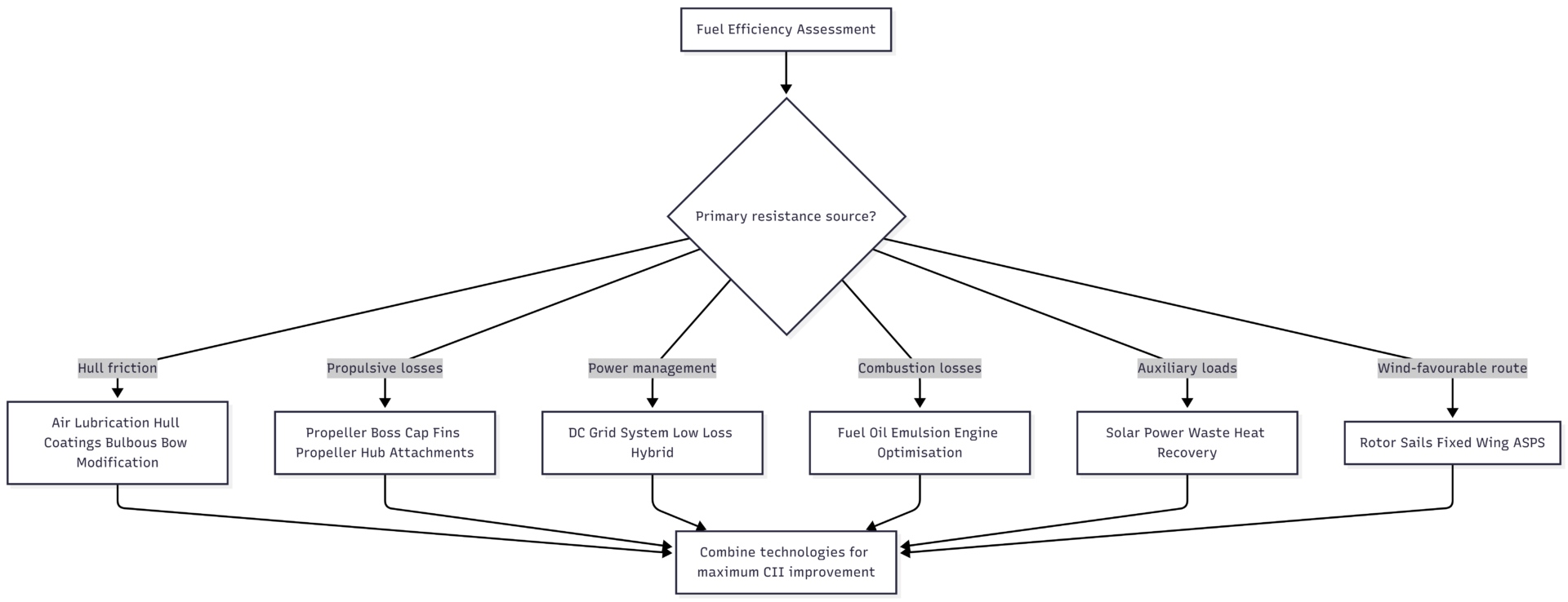
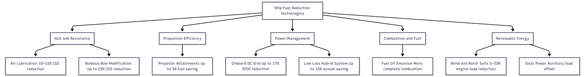
The strongest efficiency programmes combine multiple technologies. Air lubrication and bulbous bow modification address hull resistance. Propeller attachments improve propulsive efficiency. DC grid or hybrid systems optimise engine load management. Wind and solar installations reduce main engine and generator demand. A well-designed combination of these technologies can achieve 20–35% aggregate fuel reduction — sufficient to move a vessel from a D or E CII rating to an A or B.
At current bunker fuel prices, technologies with documented 10–15% fuel savings typically achieve payback periods of two to five years, with returns continuing for the vessel’s remaining service life. The economics, regulatory pressure, and operational resilience case all point in the same direction: fuel efficiency investment is no longer a question of if, but of which technologies to prioritise and in what sequence.
Happy Boating!
Share 7 Technologies To Reduce Fuel Consumption Of Ships with your friends and leave a comment below with your thoughts.
Read What To Do During Marine Auxiliary Boiler’s Flame Failure or Fuel Pump Tripping? until we meet in the next article.