What To Do During Marine Auxiliary Boiler’s Flame Failure or Fuel Pump Tripping?
A marine auxiliary boiler flame failure or fuel pump trip is one of the more urgent situations an engineer will face on watch. The boiler’s safety interlocks shut everything down automatically — but what happens next depends entirely on the engineer’s methodical response. Rush the restart and you risk a furnace explosion. Ignore the root cause and the fault repeats.
This guide covers the correct immediate response, systematic troubleshooting for both flame failure and fuel pump trips, and the specific checks that experienced engineers have used to bring recalcitrant boilers back online — including real-world diagnostics from a Saacke auxiliary boiler scenario.
Understanding the Two Failure Modes
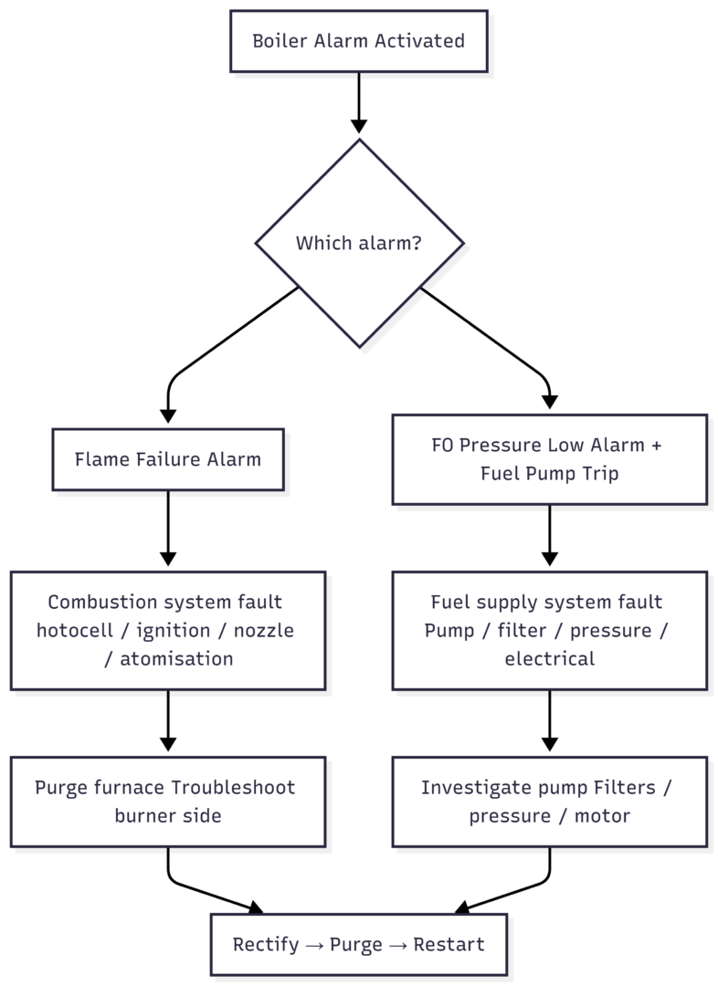
Before troubleshooting, it helps to establish which failure occurred first. The sequence matters.
Flame failure means the burner flame extinguished unexpectedly. The boiler safety system detects the loss of flame via the photocell (flame eye) and shuts off fuel supply immediately to prevent unburnt fuel accumulating in the furnace — the precondition for a furnace explosion.
Fuel pump trip means the fuel oil pump stopped, which starves the burner of fuel and causes flame failure as a downstream consequence. The root cause is in the fuel supply system, not the combustion system.
Immediate Response: Safety First
Regardless of which failure occurred, the immediate sequence is the same.
Step 1 — Confirm the Burner Is Off
The boiler interlock should have stopped the burner automatically. Verify this physically — do not assume the automatic shutdown was successful.
Step 2 — Do Not Attempt an Immediate Restart
This is the most critical point. A flame failure alarm is a safety signal, not an inconvenience. Unburnt fuel or fuel vapour may be present in the furnace. Attempting to restart before purging creates the conditions for a furnace explosion.
Never bypass or override flame failure trips or safety interlocks under any circumstances.
Step 3 — Purge the Furnace
Run the forced draught (FD) fan for a minimum of 5–10 minutes with the burner off. This clears any unburnt fuel vapour from the furnace and flue gas path before any ignition attempt.
Some boiler management systems automate this purge sequence — but always verify it has actually completed rather than assuming the system has run through it correctly.
Step 4 — Inform and Log
Notify the duty engineer or chief engineer. Record the alarm time, conditions, and all actions taken in the engine room logbook. This record matters if the fault recurs or if the boiler requires third-party inspection.
Troubleshooting Flame Failure
Once the furnace is purged and it is safe to investigate, work through the combustion system systematically.
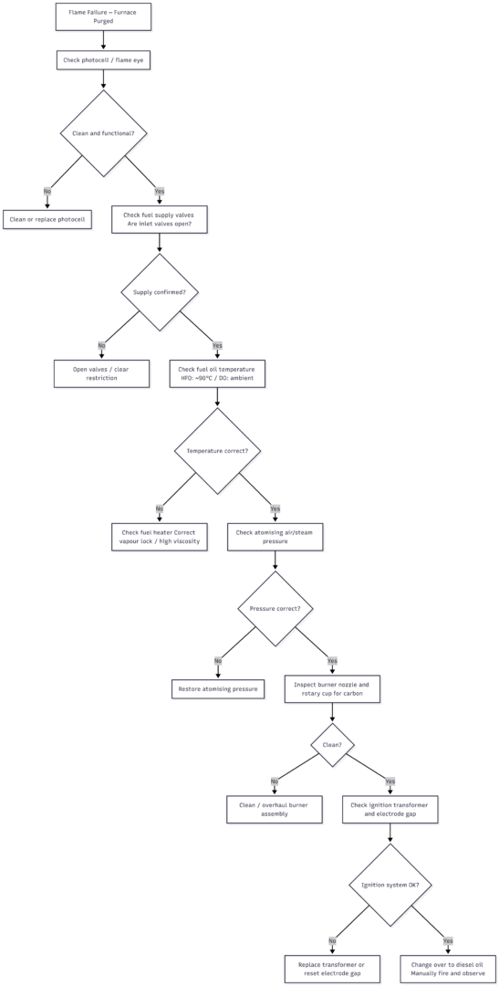
Photocell (Flame Eye)
The photocell detects the presence of flame. If it is coated with carbon deposits or has deteriorated, it will fail to detect a flame that is actually burning — causing a false flame failure trip — or it will fail to detect an actual extinction. Clean the photocell lens first; replace the unit if cleaning does not resolve the fault.
Fuel Oil Temperature and Viscosity
For HFO-fired boilers, fuel oil temperature at the burner should be approximately 90°C. Below this temperature, viscosity is too high for proper atomisation — the fuel cannot be broken into the fine droplets required for complete combustion, and the flame becomes unstable or fails to ignite.
Conversely, excessively high temperature causes vapour lock — fuel flashes to vapour before it reaches the nozzle, creating an air gap in the supply line and starving the burner. Check the fuel oil heater for correct operation in both directions.
Atomisation
Poor atomisation is a common cause of flame failure that does not always generate an obvious alarm. Check atomising steam pressure (or atomising air pressure, depending on the burner type). Low atomising pressure produces large fuel droplets that burn poorly or not at all.
Burner Nozzle and Rotary Cup
Carbon deposits accumulate on nozzles and rotary cups over time, partially blocking the fuel orifice and disrupting the spray pattern. If the boiler fires successfully on diesel oil (DO) but fails on HFO, a partially blocked nozzle is a likely cause — HFO is less forgiving of restriction than the lighter, lower-viscosity diesel. Overhaul the burner assembly, clean the nozzle, and inspect the rotary cup if fitted.
Ignition System
A faulty ignition transformer or incorrect spark electrode gap will prevent ignition even when fuel supply and atomisation are correct. Check the transformer output and verify the electrode gap against the manufacturer’s specification. The gap is typically in the range of 3–6 mm but varies by boiler make.
Troubleshooting Fuel Pump Tripping
When the fuel pump trips, the boiler loses its fuel supply and flame failure follows. The fuel pump itself may be the primary fault, or the trip may be caused by conditions upstream or downstream of the pump.
| Possible Cause | Check | Corrective Action |
|---|---|---|
| Motor overload trip | Motor breaker / overload relay | Reset after identifying cause; check OCR setting |
| Pump mechanical seizure | Can pump shaft be rotated by hand? | Free off or replace pump |
| Blocked suction filter (dirt trap) | Remove and inspect fine filter | Clean filter element |
| Air in suction line | Bleed point on suction | Bleed air from system |
| Wrong fuel temperature / viscosity | Fuel oil temperature reading | Correct heater operation |
| Faulty pressure transmitter | Check wiring; calibrate transmitter | Calibrate to 4–20 mA output; replace if failed |
| Blocked fuel oil line (back pressure) | Local pressure gauge reading | Clear restriction; check return/supply valves |
| Motor winding fault | Megger reading on pump motor | Repair or replace motor |
| Both pumps tripping | Pressure switch or system back pressure | Inspect pressure switch; clear system restriction |
Pressure Transmitter and PLC Faults
The PLC (Programmable Logic Controller) governs the boiler’s automatic firing sequence. If a pressure transmitter provides incorrect feedback — due to a wiring fault, calibration drift, or a blocked impulse line — the PLC will interpret the reading as a low-pressure condition and command the pump to stop.
Check the wiring to the pressure transmitter first. If the wiring is intact, calibrate the transmitter using a master calibrator; the output should read between 4 and 20 mA across the operating range. A local pressure gauge (new or calibrated) fitted alongside the transmitter gives an independent reading for comparison.
Note: the pressure transmitter for diesel oil (DO) is typically a separate unit from the HFO transmitter. When changing over between fuels, confirm which transmitter is active in the PLC logic.
The PLC itself has a reset function that restores default values — this resolves some software-state faults without requiring hardware investigation. Check the PLC or logic module display for any error codes and consult the boiler manufacturer’s fault code documentation.
Fuel Oil Pressure Settings
Fuel oil pressure at the burner should be maintained between 2 and 4 bar for HFO operation. Outside this range:
- Too high: Excess fuel disrupts the air-fuel ratio, producing a rich mixture and potentially overloading the burner
- Too low: Lean mixture, unstable flame, and flame failure
Near the fuel changeover valves and burner assembly, there are pressure regulating valves for both HFO and MDO lines. Adjust these to bring burner pressure within the 3–4 bar range for HFO. A fine adjustment valve near the burner pressure gauge allows final trimming.
If the system uses a three-way changeover valve between HFO and MDO circuits, confirm it is set to the correct position for the fuel being burned.
Real-World Scenario: Saacke Boiler Troubleshooting
The following checklist is drawn from a documented troubleshooting case on a vessel fitted with a Saacke auxiliary boiler. The boiler shut down on flame failure alarm, failed to restart on HFO, and was changed over to diesel for manual firing. FO pressure low alarms continued and fuel pumps were tripping.
The systematic checks that resolved the fault:
- Verified FO pressure setting — confirmed burner pressure within 2–4 bar range
- Checked both fuel pumps for mechanical freedom — rotated shaft by hand to confirm no seizure
- Checked overcurrent relay (OCR) setting and adjusted as required
- Cleaned the fine filter (dirt trap) on the burner supply line
- Checked pressure transmitter wiring and calibrated — confirmed 4–20 mA output
- Confirmed DO pressure transmitter (separate from FO unit) was operational
- Reset the PLC — restored default logic values
- Checked fuel oil temperature — confirmed heater operating at ~90°C for HFO
- Inspected nozzle for partial blockage — cleaned to clear back pressure
- Checked megger reading on pump motor — confirmed winding integrity
- Checked suction line and return line changeover valves for correct position
- Started second fuel pump — confirmed fault isolated to first pump
- Overheated burner assembly — confirmed nozzle was creating back pressure when partially blocked
Note: Specifics may differ depending on boiler manufacturer, automation system, and vessel piping arrangement.
Restart Procedure
Once the root cause is identified and corrected:
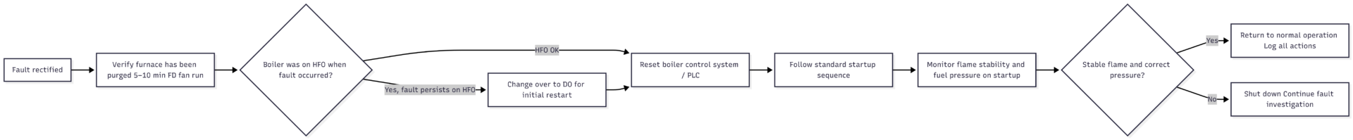
Key restart rules:
- Always complete the furnace purge before any ignition attempt
- Do not bypass any safety interlock at any stage
- If the boiler will not restart on HFO, change over to diesel oil — it is easier to ignite and will confirm whether the combustion system is functional while the HFO system is further investigated
- Log all actions taken and report to the chief engineer
Common Causes Summary
| Fault | Primary Causes | First Checks |
|---|---|---|
| Flame failure — combustion side | Dirty photocell, low fuel temperature, blocked nozzle, failed ignition | Photocell condition, fuel temperature, nozzle inspection |
| Flame failure — supply side | Low FO pressure, air in line, blocked filter | Fuel pressure gauge, filter condition, bleed points |
| Fuel pump trip — electrical | Overload relay, motor winding fault | Motor breaker, OCR setting, megger reading |
| Fuel pump trip — mechanical | Pump seizure, blocked filter, back pressure | Shaft rotation by hand, filter, nozzle/line back pressure |
| Fuel pump trip — instrumentation | Faulty pressure transmitter, PLC state | Transmitter calibration, PLC reset, error codes |
| Both pumps tripping | Pressure switch fault, system back pressure | Pressure switch, system restriction, nozzle condition |
Preventive Maintenance
The majority of auxiliary boiler flame failures and fuel pump trips are preventable through consistent maintenance. The auxiliary boiler is idle at sea when the exhaust gas boiler covers steam demand — which means its burner and fuel system can deteriorate unnoticed between port calls.
Routine tasks that prevent most failures:
- Clean burner filters (dirt traps) regularly — blocked filters are the single most common cause of fuel pressure problems
- Inspect and clean nozzles during each burner overhaul — partial blockage creates back pressure and unstable flame
- Test photocell/flame eye function during planned maintenance — not just when a failure occurs
- Verify pressure transmitter calibration at intervals specified by the PLC manufacturer
- Test safety trips and interlocks as part of the planned maintenance system (PMS) — flame failure trips, fuel pump trips, and low-pressure cutouts must all function correctly
- Check fuel oil heater performance — correct viscosity at the burner depends entirely on consistent heating
Auxiliary boiler flame failures almost always trace back to one of a small number of causes: dirty filters, a blocked nozzle, a failed photocell, or a fuel temperature problem. Disciplined burner routines and filter cleaning eliminate most of these before they become operational failures.
Happy Boating!
Share What To Do During Marine Auxiliary Boiler’s Flame Failure or Fuel Pump Tripping? with your friends and leave a comment below with your thoughts.
Read What is a Bearing Scraper? until we meet in the next article.