Important Things To Check In Ship’s Engine Bedplate
The bedplate is the foundation of a marine engine. Every structural load the engine generates — the static weight of the engine block, the dynamic forces from pistons and connecting rods, propeller thrust transmitted through the crankshaft — passes through the bedplate before reaching the ship’s hull structure. If the bedplate develops a fault, the consequences cascade upward through the entire engine: crankshaft misalignment, main bearing failure, heavy vibration, and in serious cases, complete engine failure.
Despite its critical role, the bedplate is one of the least accessible parts of a marine engine, located at the very bottom of the engine room in the bilge section where it is exposed to oil, water, and difficult working conditions. This is precisely why systematic inspection matters. Faults that are caught early — a developing crack, a loose holding-down bolt, early-stage corrosion — can be corrected without major disruption. Faults that are missed can disable a ship’s propulsion system at sea.
What the bedplate is and what it does
The bedplate is the lowermost structural component of both two-stroke and four-stroke marine engines. For large slow-speed engines, it is typically a fabricated steel structure assembled from prefabricated sections during installation. For smaller engines, it may be a single cast-iron component. Large engine bedplates use low-carbon steel with a maximum carbon content of 0.23%, which provides the combination of strength, weldability, and resistance to brittle fracture that the application demands. Small engine bedplates use cast iron, which has inherent vibration-damping properties that reduce the frequency and severity of fatigue cracking.
The structural anatomy of a bedplate consists of two longitudinal girders running the full length of the engine, connected by transverse girders positioned between each throw of the crankshaft. The transverse girders carry the main bearing saddles — the pockets in which the crankshaft main bearings sit — and the tie bolt connections that secure the bedplate to the A-frame and cylinder block above. On modern engines, the transverse girders are cast steel sections with the bearing pockets machined to fine tolerances, welded into the fabricated longitudinal girder structure. After manufacture, the entire bedplate is stress-relieved and the bearing pockets are line-bored to ensure the crankshaft sits in perfect alignment across all bearing positions.
The bedplate serves seven distinct structural and operational functions simultaneously.
| Function | Description |
|---|---|
| Static load support | Supports the dead weight of the stationary engine frame and block |
| Dynamic load support | Absorbs and distributes the cyclic forces from running gear during operation |
| Crankshaft alignment | Holds the crankshaft in precise alignment through the main bearing saddles |
| Load distribution | Transmits engine loads to the ship’s tank top structure |
| Oil collection | Collects crankcase lube oil and transfers it to the sump for recirculation |
| Thrust transmission | Fastens the engine to the tank top and transmits propeller thrust to the hull |
| Hull contribution | Contributes to the longitudinal strength of the engine room bottom structure |
The bedplate must be rigid enough to maintain crankshaft alignment under full engine load, yet flexible enough to hog and sag with the ship’s hull in a seaway. Too rigid, and hull flexing will snap holding-down bolts or crack the bedplate itself. Too flexible, and crankshaft misalignment will destroy main bearings. This balance is achieved through careful material selection, construction geometry, and holding-down bolt arrangement.
The six critical inspection areas—
1. Cracks
Cracking is the most serious and most common structural problem found in engine bedplates. The cyclic nature of engine loading — high-pressure combustion forces transmitted through pistons, connecting rods, and crankshaft to the bearing saddles, repeated hundreds of times per minute for years — creates fatigue conditions in the steel. Cracks begin at stress concentration points and propagate under continued loading.
Five specific locations require close examination during every bedplate inspection.
Weld joints between transverse and longitudinal girders are the highest-risk locations. The junction between perpendicular structural members creates a stress concentration, and any weld imperfection — incomplete fusion, undercut, porosity — acts as a crack initiation site. Cracks at these welds typically run parallel to the weld toe or through the heat-affected zone.
Under and around the bearing pockets in the transverse girders is the second critical zone. The main bearing saddles see the full dynamic load of combustion with every engine cycle. Cracks here may be radial (radiating outward from the bearing pocket center) or circumferential (following the contour of the pocket). Either pattern indicates fatigue progression and requires immediate attention.
Tie bolt and frame bolt holes are another concentration point. The bolt holes interrupt the continuous steel section, and the stress concentration factor around a hole can be two to three times the nominal stress in the surrounding material. Radial cracking originating from bolt holes is a recognized failure mode.
Lightening holes in the bedplate structure and girder webs are designed to reduce weight, but they also create stress concentrations. Cracks can develop around the periphery of these holes under repeated loading.
The base of main bearing keeps (the cap structures that retain the main bearing shells in the saddle) should be inspected for cracking at the fillet radii where the keep meets the bedplate structure.
When cracks are suspected, crack detection techniques including magnetic particle inspection (MPI) or dye penetrant testing should be used rather than relying on visual examination alone. Small fatigue cracks in the early stages of propagation may not be visible to the naked eye but will respond clearly to dye penetrant.
2. Holding-down bolts
Holding-down bolts secure the bedplate to the ship’s tank top structure and are the mechanical interface through which propeller thrust is transferred from the engine to the hull. A loose or failed holding-down bolt changes the load distribution across the bedplate, increasing the load on adjacent bolts and the bedplate structure itself, which accelerates fatigue crack development.
The inspection covers several failure modes. Looseness is detected by checking bolt tension against the torque values specified in the engine manufacturer’s manual. Fretting — the micro-movement and wear at the contact surfaces between the bolt, bedplate, and chock — leaves distinctive reddish-brown oxide debris and produces visible wear marks. Shearing is a catastrophic failure where the bolt has fractured across its cross-section, typically at a thread root or at the transition between the threaded and unthreaded sections.
The recommended practice is to mark holding-down bolt nuts and the bedplate surface with reference lines so that any rotation of the nut over time — indicating loosening — is immediately visible without the need for torque checking every inspection.
Chocks — the precision machined steel or epoxy resin pads fitted between the bedplate and tank top to distribute the bolt load and compensate for surface irregularities — should also be inspected for cracking, fretting, or extrusion, particularly if looseness has been found in the holding-down bolts above them.
3. Loose frames and tie rods
The bedplate does not function in isolation. It is held together with the A-frame (cylinder frame) and the entablature (cylinder block) above it by long tie rods that run through the entire engine height. These tie rods keep the engine structure in compression, counteracting the tendency of combustion pressure to separate the components. A loose tie rod allows relative movement between the bedplate and the frame above it, which generates fretting and ultimately cracking at the joint faces and at the bolt holes.
Tie rod tension must be checked according to the manufacturer’s specification, typically using hydraulic tensioning tools that apply a defined stretch to the rod before the nut is locked. The achieved elongation — measurable with a micrometer across the rod end — confirms that the correct pre-tension has been applied.
The inspection should also check the contact faces between the bedplate and the A-frame for any signs of relative movement: fretting marks, displaced paint or coating, or metallic debris at the joint faces.
4. Oil leakages
The bedplate is the low point of the lubricating oil system. All crankcase lube oil drains by gravity through the bedplate to the sump, from where it is pumped back to the engine through the lube oil circuit. The bedplate therefore contains oil under standing head pressure at all times during operation, and any crack or joint failure creates a leak path.
Leakages can occur at the welded construction joints within the bedplate structure, at the joint face between the bedplate and the A-frame above (where joint face distortion or inadequate sealing allows oil to seep out), and at the seal faces of sensors, drain plugs, or instrumentation fittings installed in the bedplate.
Oil leaks in the bilge section of the engine room present both a fire risk and a pollution risk. Any identified leak must be traced to its origin and rectified. A leak at the bedplate-to-frame joint face that appears minor may indicate that the frame is not sitting correctly on the bedplate — a condition that also affects crankshaft alignment.
5. Corrosion
The bedplate sits in the bilge region of the engine room, the lowest point of the ship, where oil and water accumulate. Leaking hydraulic lines, condensation from temperature changes, sea water intrusion from deck leaks, and lube oil contaminated with water all contribute to a corrosive environment at the bedplate surface and in any internal pockets or recesses.
Corrosion reduces the effective wall thickness of the steel, weakening the structure and reducing its fatigue life. In severe cases, through-corrosion creates additional oil leak paths or compromises the structural integrity of the bearing pockets.
External corrosion is assessed visually, but internal corrosion in oil recesses and structural pockets requires cleaning before inspection. Ultrasonic thickness measurement using a calibrated gauge is the standard method for quantifying metal loss in suspect areas. Measurements are compared against the original design thickness recorded in the classification survey records. If remaining thickness falls below the acceptable minimum, the structure must be repaired by welding or cropping and insert plating before the engine can return to service at full rating.
Internal surfaces should be protected with appropriate coatings — epoxy-based, graphite suspension, or linseed oil — during repair or overhaul to slow the rate of future corrosion.
6. Welding and casting faults
Newly delivered engines and engines that have undergone recent weld repairs require specific attention to manufacturing or repair quality. Welding faults — incomplete fusion, undercutting, porosity, excessive heat input — may not cause immediate structural failure but create stress concentrations that initiate fatigue cracks during service.
On cast iron bedplates, casting defects including shrinkage voids, cold shuts, and internal porosity are potential crack initiation sites. These defects may not be visible externally and require non-destructive testing — dye penetrant, magnetic particle, or ultrasonic examination — for confident detection.
After any weld repair to a bedplate, the repaired area must be stress-relieved and the weld geometry examined to confirm it meets the classification society requirements in terms of weld profile, surface finish, and absence of undercut.
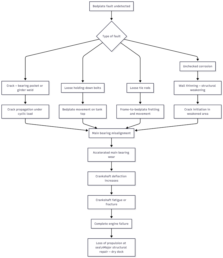
Consequences of missed bedplate faults
Inspection intervals and documentation
Bedplate inspection is a planned maintenance system (PMS) item and is also subject to class survey requirements. The inspection frequency depends on engine type, age, and operating history, but the following minimum practices apply on most vessels.
| Inspection type | Frequency | Method |
|---|---|---|
| Visual bilge inspection — oil leaks, corrosion | Every watch / daily | Visual |
| Holding-down bolt check | Every voyage / monthly | Visual marking check, torque check as required |
| Tie rod tension check | After major overhaul or as per PMS | Hydraulic tensioning tool, elongation measurement |
| Bedplate crack inspection | Annual or per class interval | Visual + dye penetrant or MPI at critical areas |
| Ultrasonic thickness measurement | On corrosion indication, or per class | Calibrated UT gauge, multiple measurement points |
| Full internal inspection | As per classification society survey | Cleaning, visual, NDT, thickness measurement throughout |
Every inspection must be documented with findings, measurements taken, and corrective actions completed. Classification surveyors reviewing maintenance records look for evidence of systematic inspection and prompt rectification. An engine bedplate with an incomplete maintenance history is a liability during class renewal surveys, even if no active fault is present.
The bedplate will outlast most other engine components if inspected properly and consistently. The failure modes are well understood, the inspection methods are straightforward, and the corrective actions — bolt tensioning, weld repair, coating, corrosion treatment — are within the capability of shipboard engineering teams with proper tools and materials. What makes the difference is the discipline to inspect every location at every interval, and to act on findings immediately rather than deferring them.
Happy Boating!
Share Important Things To Check In Ship’s Engine Bedplate with your friends and leave a comment below with your thoughts.
Read How Ballast Water Treatment System Works? until we meet in the next article.