Compressed Air Line On Ships – A General Overview
When a ship lies dead in the water — main engine off, auxiliaries silent, every system dormant — the first thing needed to restore life is compressed air. Before fuel burns, before propellers turn, before a single control system responds, compressed air must be available. It starts the engines that generate electricity, operates the valves that control fuel flow, and powers the tools that keep everything running. Without a functioning compressed air system, a modern merchant vessel cannot operate.
This article covers the complete compressed air network on ships: how it is generated, stored, distributed, and maintained, with the specifications and regulatory requirements every marine engineer needs to know.
The three compressed air systems on board
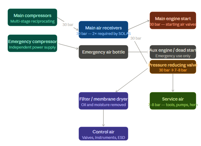
A ship’s compressed air network is not a single pipeline but three distinct systems serving different purposes at different pressures.
Main starting air (30 bar) is high-pressure air used exclusively to start the main engine and, on some vessels, auxiliary engines. The volumes and pressures involved are substantial — enough to overcome the compression resistance of a large two-stroke diesel engine and rotate it to firing speed.
Service air (7–8 bar) is working pressure air reduced from the main system through pressure reducing valves. It serves a wide range of shipboard functions including auxiliary engine starting, emergency generator starting, fog horn operation, fresh water and drinking water hydrophore charging, main engine turbocharger dry washing, exhaust valve spring air, sewage treatment plant aeration, boiler soot blowing, pneumatic oil transfer pumps, and general maintenance work such as cleaning, painting, chipping, and pneumatic tool operation.
Control air (7–8 bar, filtered) is a branch of the service air system that has been passed through additional filters and membrane dryers to remove all traces of moisture and oil. This ultra-clean air powers pneumatic controllers, instrumentation, automatic valves, combustion control systems, emergency shutdown systems on gas tankers, and quick-closing valve operation. Because it feeds sensitive equipment with small orifices, rubber diaphragms, and close-tolerance spools, contamination in control air causes failures that can disable critical safety systems.
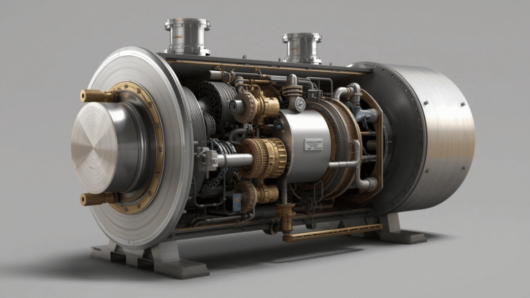
Main air compressor
The main air compressor is the source of the entire system. It compresses atmospheric air by reducing its volume, raising pressure progressively through multiple stages until discharge pressure reaches 30 bar.
Most modern merchant vessels use multi-stage reciprocating compressors with intercoolers between each compression stage and an aftercooler at discharge. Intercoolers remove the heat generated by compression between stages, which improves efficiency and reduces the temperature of air entering the next stage. Aftercoolers drop discharge temperature before the air enters the receiver. Auto-drain arrangements at each cooling stage remove the condensate that forms as compressed air cools.
Compressor capacity is measured in Free Air Delivery (FAD) — the volume of air, expressed in cubic metres per hour, that the compressor actually delivers when measured at atmospheric pressure and temperature. FAD is the meaningful comparison figure because it accounts for volumetric efficiency losses.
A vessel may carry two or three main compressors depending on main engine displacement, total air demand, and whether the ship carries soot blowing equipment on boilers or economizers, which increases air consumption significantly.
SOLAS requirement: Main air compressors must be capable of filling the ship’s air receivers from 0 to maximum working pressure (30 bar) within one hour.
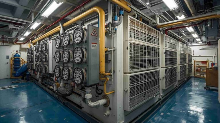
Main air receivers (air bottles)
Air receivers store high-pressure compressed air for instantaneous large-volume demand — the kind of demand created when a starting air valve opens to a main engine cylinder. No compressor can deliver air fast enough to start a large diesel engine directly; the receiver is the buffer that makes this possible.
Every ship carries two main air receivers of identical capacity, plus one emergency air bottle. The two-receiver requirement provides redundancy — if one receiver is isolated for maintenance or inspection, the other maintains starting capability.
| Specification | Requirement |
|---|---|
| Working pressure | 30 bar |
| Hydraulic test pressure | 1.5 × working pressure (45 bar) |
| Minimum starts — reversible engine | 12 consecutive starts |
| Minimum starts — non-reversible engine | 6 consecutive starts |
| Periodic hydraulic test interval | Every 10 years (large receivers) |
| Fill time from 0 to max pressure | Within 1 hour |
| Internal coating | Anti-corrosive (epoxy, graphite suspension, linseed oil, or copal varnish) |
Mountings required on every air receiver
Each receiver is fitted with a specific set of safety and operational devices:
Fusible plug — made of an alloy of bismuth (50%), tin (30%), and lead (20%), with a melting point of approximately 104°C (220°F). Fitted at the bottom of the receiver or at the ship’s side, it releases compressed air if temperature rises abnormally, preventing pressure vessel failure from heat.
Atmospheric relief valve — provides overpressure protection and serves as backup to the fusible plug. Before CO₂ flooding of the engine room in a fire, this valve must be opened manually to prevent over-pressurization of the receivers from heat exposure.
Spring-loaded safety valve — set at 32 bar for a 30-bar system, with 10% or greater pressure accumulation tolerance. This is the primary overpressure protection during normal compressor operation.
Compensation rings — structural flanges fitted around any hole cut into the pressure vessel wall to restore the integrity lost by the opening. Valves and fittings are mounted on compensation rings.
Manual or automatic drain valve — removes condensate accumulated at the receiver bottom. In humid conditions this may require manual operation two to three times daily.
Pressure gauges, access doors, and main starting valve connections complete the standard fitment.
Air receiver inspection and maintenance
Moisture is the primary enemy of air receivers. Even with correctly functioning compressor drains and aftercoolers, significant condensate accumulates inside receivers, particularly in tropical and humid operating conditions. Moisture promotes corrosion, and the worst corrosion is typically found at the lowest point of the receiver near the drain outlet.
Inspection procedure involves draining and entering the receiver (where size permits), conducting a thorough visual inspection of all internal surfaces and welds, and using an ultrasonic thickness gauge to measure wall thickness at any area showing surface corrosion. If measured thickness is below the minimum allowable, the working pressure of that receiver must be reduced proportionally. This requires recalibrating the compressor cut-in and cut-off pressure settings when that receiver is in use and adjusting the safety valve setting accordingly. Alternatively, the receiver can be isolated from service and used only under manual supervision.
Receivers too small for entry must be inspected using cameras on flexible probes. All longitudinal and circumferential weld seams must be examined. Large cylindrical receivers are typically fabricated with machine-welded seams, stress-relieved at approximately 600°C, and radiographed during manufacture. All fabrication and inspection records should be maintained in the vessel’s planned maintenance system.
Service air system
Service air is the general working pressure supply of the ship, reduced from 30 bar to 7–8 bar through a pressure reducing valve on the main air line. Its applications cover most of the ship’s operational requirements outside engine starting.
Key service air consumers include: auxiliary engine and emergency generator starting, fog horn and whistle operation, main engine exhaust valve spring air, turbocharger dry washing, boiler and economizer soot blowing, sewage treatment plant aeration, pneumatic pump operation for fuel and lube oil transfers, and all maintenance air for pneumatic tools — grinders, chisels, needle guns, impact wrenches, and painting equipment.
Service air is also used for charging fresh water and drinking water hydrophores — the pressurized tanks that maintain water supply pressure throughout the vessel without running pumps continuously.
Control air system
Control air shares the same pressure as service air (7–8 bar) but differs entirely in quality. It is taken as a branch from the service air system and passed through a dedicated filtration and drying train before entering the control air distribution network.
The sensitivity of pneumatic control equipment makes contamination a serious operational risk. Oil and water emulsions cause rubber diaphragms and valve spools to swell, stick, or deteriorate. Rust particles from inadequately dried air abrade close-tolerance components. Small orifices in control valves and positioners block with combined oil-water-particulate contamination. Any of these failures can disable automatic valves, instrument controllers, or safety shutdown systems.
Control air filter and dryer arrangement
A typical control air treatment train consists of three stages: a primary line filter that removes coarse particles — rust, dust, and debris — down to approximately 5 microns; a coalescing secondary filter that captures water droplets and oil mist down to 0.3 microns by causing fine droplets to merge into larger drops that drain away; and a membrane hollow-fibre dryer that removes dissolved moisture from the air stream by selective diffusion through polymer membranes.
A differential pressure gauge monitors the condition of the primary and secondary filters. Rising differential pressure indicates increasing contamination and approaching saturation — the filter elements must be replaced before the differential pressure reaches the maximum rated value. Membrane dryer elements are replaced on schedule as defined in the planned maintenance system, not on condition alone, since membrane degradation is not always reflected in differential pressure.
A small plastic float and auto-drain arrangement at the line filter handles routine moisture removal. In high-humidity conditions or tropical ports, manual draining may be necessary in addition to the auto-drain.
Emergency air compressor and emergency air bottle
The emergency compressed air system is designed specifically for the dead ship scenario — when all main power is lost, all receivers are depleted, and there is no conventional means of starting any engine.
The emergency air compressor is an independent unit with its own power supply, either a dedicated diesel engine or connection to the emergency switchboard. It is sized to fill the emergency air bottle to a pressure sufficient to start at least one auxiliary engine, which in turn restores electrical power and begins recharging the main receivers.
A separate emergency QCV (quick-closing valve) air bottle, maintained at 7 bar, is the dedicated supply for emergency operations. In the event of an uncontrollable engine room fire, compressed air from this bottle actuates quick-closing valves on all fuel oil and lubricating oil tank outlets and closes funnel and blower dampers. This cuts off all fuel and air supply to the engine room, starving the fire of both.
Control air is also used in Emergency Shutdown Systems (ESDS) on gas tankers, where pneumatic actuation of multiple safety valves must occur simultaneously and reliably on a signal from bridge or cargo control room.
System specifications summary
| Parameter | Specification |
|---|---|
| Main starting air pressure | 30 bar |
| Service air pressure | 7–8 bar |
| Control air pressure | 7–8 bar (filtered, dry) |
| Safety valve set pressure | 32 bar (for 30-bar system) |
| Fusible plug melting point | ~104°C (220°F) |
| Fusible plug composition | Bismuth 50%, Tin 30%, Lead 20% |
| Air receiver test pressure | 1.5 × working pressure |
| SOLAS starts — reversible | 12 minimum |
| SOLAS starts — non-reversible | 6 minimum |
| Compressor fill time (0 to 30 bar) | Within 1 hour |
| Control air filter — coalescing stage | 0.3 micron |
| Periodic hydraulic test | Every 10 years |
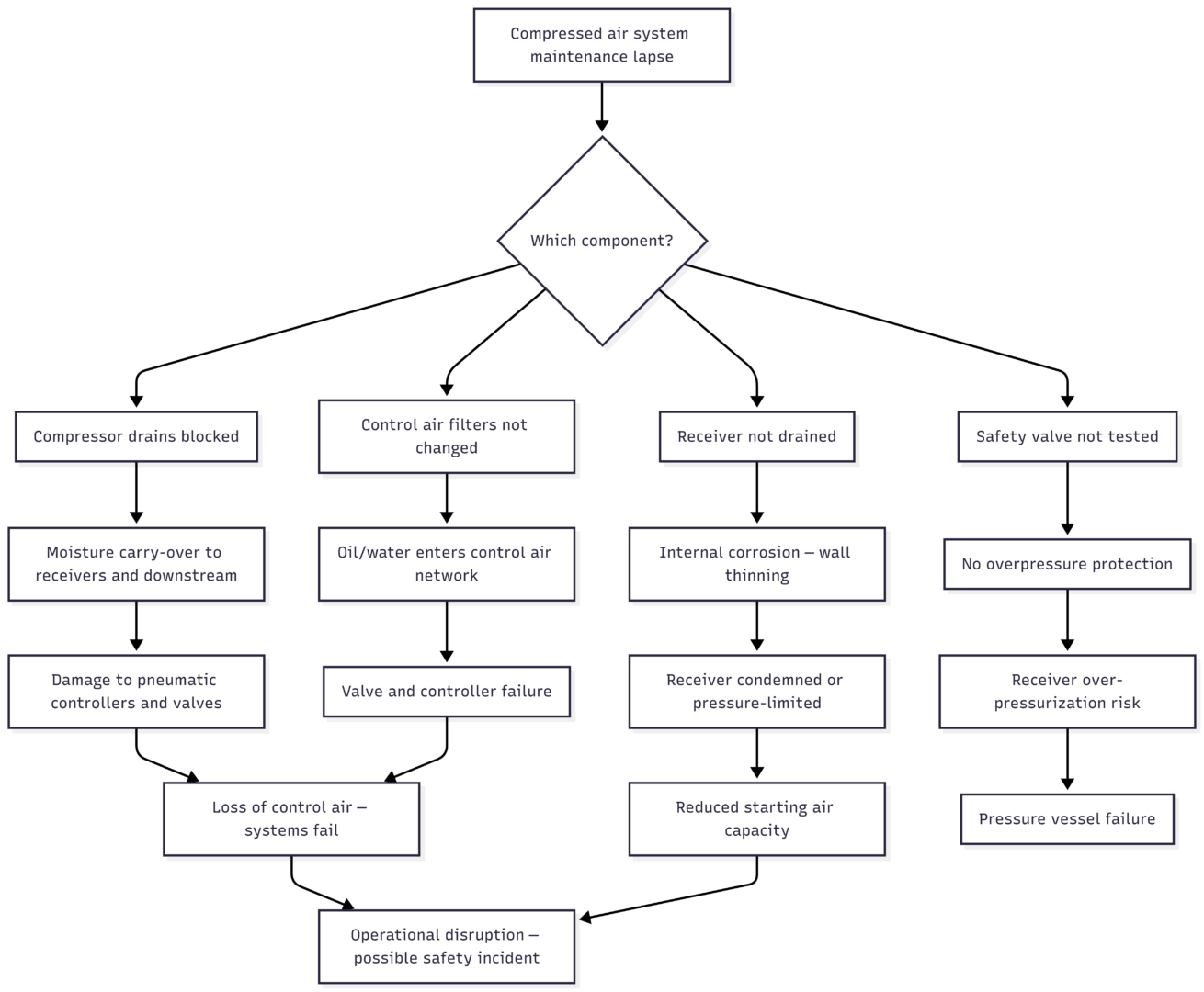
Common maintenance failures and their consequences
Key maintenance practices
Routine compressed air system maintenance is not complicated, but it must be consistent. Receiver drains should be checked every watch in humid conditions and drained as required — in extreme humidity, this can mean two to three times daily. Compressor inter-stage and aftercooler drains must function correctly at every compression cycle, and their operation should be confirmed visually during rounds.
Control air filter differential pressure should be logged at regular intervals and filters replaced on schedule without waiting for symptoms to appear. Membrane dryer elements follow a fixed replacement interval regardless of apparent condition.
Safety valve function is confirmed during annual or voyage surveys, but the seating condition should be visually checked during regular inspections. Fusible plugs should be inspected and replaced on schedule — they are single-use safety devices that must be in serviceable condition at all times.
Pre-departure checks should confirm receiver pressures are at operating level, that both main receivers and the emergency bottle are charged, that auto-drain arrangements on compressors and filters are functional, and that compressor cut-in and cut-off pressure settings are correct for the calibrated safety valve settings on each receiver.
The compressed air system touches nearly every operational function on the ship. Its reliability depends not on complexity but on disciplined, regular attention to the components that manage moisture, pressure, and cleanliness throughout the network.
Happy Boating!
Share Compressed Air Line On Ships – A General Overview with your friends and leave a comment below with your thoughts.
Read 8 Common Problems Found In Steering Gear System Of Ships until we meet in the next article.