Blow-Down Procedure for Marine Boilers
The marine boiler is one of the most maintenance-intensive systems on any ship, and blow-down is one of the most important routine procedures that keeps it operating safely and efficiently. Performed incorrectly or too infrequently, the build-up of dissolved and suspended solids inside the boiler leads to scale formation, corrosion, tube overheating, and steam contamination. Performed correctly and on schedule, blow-down extends boiler life, protects the steam system downstream, and maintains heat transfer efficiency throughout the vessel.
This guide covers why blow-down is necessary, the two types of blow-down and when each applies, the full step-by-step valve procedure, the regulatory requirements governing discharge, and practical guidance on minimising blow-down frequency through water treatment and automation.
Why Boiler Blow-Down Is Necessary
Boiler water is never chemically pure. Even treated feed water carries dissolved minerals, salts, and trace contaminants — collectively measured as Total Dissolved Solids (TDS). When the boiler heats water and converts it to steam, the steam itself carries very little of this dissolved material. The solids remain behind in the boiler water and concentrate over time as the evaporation cycle continues.
The consequences of allowing TDS levels to rise unchecked are progressive and serious:
Heavier particles and precipitates settle to the bottom of the boiler shell, forming a sludge layer. This sludge insulates the boiler’s heating surfaces from the water, reducing heat transfer and causing the metal beneath to overheat. Sustained overheating weakens tube material and can lead to tube failure.
Scale forms on internal surfaces when calcium and magnesium compounds precipitate out of solution. Even a thin layer of scale dramatically reduces thermal efficiency — scale has roughly forty times the insulating effect of steel, meaning that scaled tubes require significantly more fuel to produce the same steam output.
Suspended solids, oils, and foam on the water surface get carried over with the steam into the steam distribution system and heat exchangers. Contaminants in steam degrade the performance of heat exchangers, heating coils, and turbines.
Oil ingress — most commonly from a leaking heat exchanger — presents a particular hazard inside the boiler. Oil floats on the boiler water surface and can be carried into steam lines or, in severe cases, foul boiler surfaces sufficiently to cause a fire risk.
Blow-down addresses all of these problems by physically removing contaminated water from the boiler and allowing it to be replaced with fresh, treated feed water.
Two Types of Marine Boiler Blow-Down
There are two distinct blow-down points on a marine boiler, each targeting different types of contamination.
Bottom Blow-Down
The bottom blow-down valve is located at the lowest point of the boiler shell. Its purpose is to remove the heavy sludge and precipitated solids that settle to the bottom during operation. This is the standard blow-down procedure referred to when engineers discuss routine boiler blow-down. It is performed at regular intervals based on water test results and the boiler manufacturer’s operating schedule.
Scum Blow-Down (Scumming)
The scum valve is located at the water surface level inside the boiler. It is used to remove floating material — foam, oil, grease, and lighter contaminants — that accumulates on the surface of the boiler water rather than sinking to the bottom.
An important operational rule: scum blow-down must always be performed before bottom blow-down. If bottom blow-down is done first, the agitation it creates in the boiler water disturbs any oil or floating contaminants on the surface, mixing them back into the water column and making subsequent removal more difficult. Performing scumming first removes the surface layer cleanly, after which bottom blow-down can proceed without contaminating the bulk water.
Manual Versus Continuous Blow-Down
Manual (Intermittent) Blow-Down
Manual blow-down is performed by the boiler operator at scheduled intervals based on water test results and the established operating program. The operator opens the blow-down valves for a controlled duration — typically no more than one to two minutes — monitors the gauge glass throughout, and closes the valves when sufficient water has been discharged.
Manual blow-down is particularly effective for removing sludge and for dealing with oil ingress incidents where scumming needs to be carried out promptly. The primary disadvantage is heat and pressure loss: every time hot boiler water is discharged overboard, the heat energy it carries is lost, reducing boiler efficiency. Even brief manual blow-downs carry a meaningful thermal penalty if done excessively or incorrectly.
Continuous Automatic Blow-Down
Modern boilers are increasingly fitted with continuous blow-down automation. Rather than periodic manual discharge events, this system maintains a constant low-rate discharge precisely controlled by sensors that monitor boiler water TDS in real time. When TDS rises toward the upper operating limit, the automatic blow-down valve opens to discharge a small quantity of water. When TDS falls back within range, the valve modulates or closes.
The advantage of continuous blow-down is that it discharges water with maximum dissolved solid concentration — at the point when TDS is highest — with minimum volume and therefore minimum heat loss. The system optimises the trade-off between water quality control and thermal efficiency continuously, without requiring operator intervention.
Many systems fitted with continuous blow-down automation also incorporate a heat recovery unit in the blow-down discharge line. The hot discharged water passes through a heat exchanger before going overboard, transferring its heat to incoming feed water. This preheating reduces the energy required to bring feed water up to boiler temperature and partially offsets the thermal cost of the blow-down.
The blow-down percentage — the ratio of water discharged to total feed water consumed — can be calculated as:
% Blow-down = (Volume of blow-down water ÷ Volume of feed water) × 100
Keeping this percentage as low as possible while maintaining water quality within limits is the core objective of any blow-down management strategy.
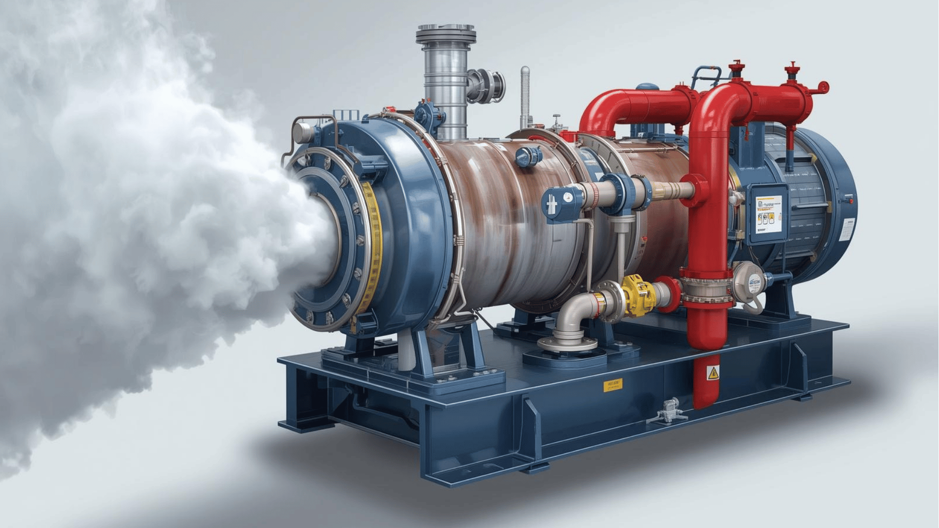
Blow-Down Valve Arrangement
Understanding the physical arrangement of the blow-down valves is essential before attempting the procedure. A standard marine boiler blow-down system has three valves in series between the boiler and the ship’s side:
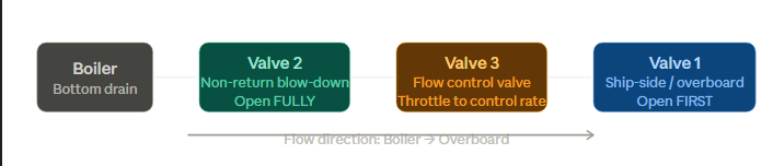
The valve closest to the ship’s side (Valve 1) is opened first in all circumstances. This is not optional — opening any downstream valve before Valve 1 creates pressure build-up in the blow-down line with no outlet, risking pipe burst or valve damage. Valve 2, the non-return valve adjacent to the boiler, is always opened fully to avoid wire drawing. Valve 3 controls the actual flow rate of the blow-down.
Step-by-Step Blow-Down Procedure
Before Starting
Inform the officer of the watch on the bridge and the duty engineer that a blow-down is about to commence. Confirm the vessel is in an area where overboard discharge is permitted (see regulatory requirements below). Verify that the boiler is operating at normal working pressure and that the water level in the gauge glass is at the correct operating level — blow-down will reduce this level and it must not fall too low during the operation.
Procedure
- Open Valve 1 (the ship-side or overboard valve) fully. This opens the discharge path to the sea.
- Open Valve 2 (the non-return blow-down valve adjacent to the boiler) fully. This valve must be opened completely — never partially throttled. Partially opening Valve 2 causes “wire drawing,” an erosion effect where high-velocity water cuts grooves into the valve seat, eventually destroying the valve’s ability to seal. All flow control must be done at Valve 3, not here.
- Use Valve 3 to control the rate of blow-down. Open it gradually and monitor the water level in the gauge glass continuously throughout the operation. Never leave the boiler unattended during blow-down.
- Continue the blow-down for the required duration — typically no more than one to two minutes for routine blow-down. The gauge glass water level must remain within safe limits at all times. If the level falls too close to the low-water alarm point, close Valve 3 immediately.
- Close the valves in reverse order: close Valve 3 first, then Valve 2, then Valve 1 last.
- After all valves are closed, check the drain pipe from the blow-down line. If it is warm or hot to the touch, one of the blow-down valves is not seating properly and is passing water. This indicates a leaking valve that must be investigated and repaired.
- Once blow-down is complete, open the belly plug (boiler drain) to remove any remaining water in the bilge area, and log the operation in the Engine Room Logbook, recording start time, stop time, and water conditions.
For Inspection Blow-Down (Emptying the Boiler)
When the boiler must be emptied for internal inspection or tube repair, the procedure differs. Stop firing and allow the boiler to cool completely before opening the blow-down valves. Open the boiler vent plug first to allow air in and prevent the formation of a vacuum as the water drains. A vacuum created by rapid steam condensation in a sealed boiler can collapse piping or cause a pipe burst.
Ensure the overboard non-return valve is functioning correctly before draining. If seawater were able to enter a hot boiler through a faulty non-return valve, the resulting rapid steam generation in the cold water creates an immediate explosion risk.
Advantages and Disadvantages of Blow-Down
| Aspect | Detail |
|---|---|
| Maintains TDS within limits | Prevents scale formation and the heat transfer losses that follow |
| Removes corrosion accelerants | Dissolved oxygen, chlorides, and other corrosive agents are discharged |
| Prevents tube scaling | Protects internal heating surfaces from insulating deposits |
| Prevents carryover | Keeps steam clean for use in heat exchangers and auxiliary systems |
| Removes surface oil and foam | Scum blow-down clears oil ingress before it contaminates the bulk water |
| Heat and pressure loss (manual) | Each manual blow-down discharges hot pressurised water — energy that must be replaced |
| Reduced efficiency if overdone | Excessive blow-down frequency reduces boiler thermal efficiency unnecessarily |
| Additional operator time (manual) | Requires supervised presence throughout the operation |
Regulatory Requirements and Discharge Restrictions
Boiler blow-down water contains treatment chemicals, dissolved solids, and potentially oily contaminants from hotwell leakage. It is not clean water and its discharge is regulated under international and national environmental frameworks.
The key requirements are:
Blow-down must not be performed in port waters. The chemical additives in boiler water — scale inhibitors, oxygen scavengers, pH conditioners — are harmful to the marine environment and their discharge in enclosed port waters is prohibited.
The vessel must comply with the Vessel General Permit (VGP) Chapter 12 requirements, which restrict overboard discharge of boiler blow-down in designated areas. Engineers must know where the vessel is operating and whether any special area restrictions apply.
The Master and officer of the watch must be notified before commencing blow-down. This is both a safety and a regulatory requirement — the bridge must know a deck-penetrating valve to the ship’s side is being operated.
Blow-down must be recorded in the Engine Room Logbook, including start time and stop time. If blow-down water or hotwell water is directed to the bilges rather than directly overboard, the transfer must be recorded in the Oil Record Book (ORB) as well.
Blow-down in territorial waters or harbour is only permissible in two situations: when the ship is entering dry dock and must empty the boiler, or for genuine safety reasons.
The only exception to the restriction on port discharge is where performing the blow-down is necessary to prevent danger to the ship or crew.
Minimising Blow-Down: Chemical Treatment and Automation
The most effective way to reduce blow-down frequency — and the associated heat, pressure, and water losses — is rigorous boiler water chemical treatment.
Regular testing of boiler water and hotwell water for TDS, pH, chloride content, dissolved oxygen, and alkalinity allows engineers to adjust chemical dosing precisely. When feed water quality is maintained within tight limits, TDS builds up more slowly in the boiler, and the intervals between necessary blow-downs extend. This directly reduces fuel consumption and water usage.
The second measure is replacing manual blow-down with an automatic continuous blow-down system. Automatic systems open and control the blow-down valve only when TDS reaches the upper limit, discharging the minimum quantity of water needed to restore quality. When combined with a heat recovery heat exchanger in the blow-down line, the thermal losses from continuous blow-down can be reduced to a small fraction of the losses incurred by manual intermittent blow-down.
The combination of disciplined water treatment and automated blow-down control represents current best practice for marine boiler water management, and provides measurable reductions in boiler operating costs across a vessel’s service life.
Happy Boating!
Share Blow-Down Procedure for Marine Boilers with your friends and leave a comment below with your thoughts.
Read A Guide to Fire Pumps on Ship until we meet in the next article.