How Spark Erosion Can Damage the Main Propulsion Engine of a Ship?
Spark erosion is a silent but destructive electrical phenomenon that targets the heart of a ship’s main propulsion engine. It occurs when stray currents from the vessel’s impressed current cathodic protection (ICCP) system discharge through the propeller shaft and into the engine bearings. The result is rapid pitting, grooving, and material loss on critical white-metal-lined surfaces, leading to accelerated wear, overheating, and in extreme cases complete crankshaft failure or crankcase explosion.
This damage is not random. It stems directly from the interaction between modern engine design, the physics of electrical arcing in oil films, and inadequate shaft earthing. Understanding the mechanism, recognizing early signs, and implementing robust prevention is essential for marine engineers responsible for propulsion reliability.
What Is Spark Erosion?
Spark erosion is the localized removal of metal caused by electrical arcing between two dissimilar current-carrying surfaces. In technical terms, when an electrical potential difference exists and the insulating medium (in this case, lubricating oil film) breaks down, a high-energy spark jumps the gap. Each spark creates a tiny crater or cavity, eroding the softer bearing material—typically white metal—through repeated micro-explosions.
On ships, the propeller, hull, bedplate, crankshaft, and bearings are constructed from different metals. The ICCP system deliberately introduces protective current into the hull and stern gear to prevent galvanic corrosion of the large exposed propeller. When the shaft rotates, the lubricating oil film in the stern tube and main bearings acts as a partial electrical insulator. Voltage builds until it exceeds the dielectric strength of the oil film, causing an arc. The propeller, being a massive cathodic surface, draws significant current that must find a return path to the hull. Without a dedicated low-resistance earthing route, that path becomes the main engine bearings.
How Spark Erosion Develops: Step-by-Step Mechanism
The process unfolds in a predictable sequence:
- ICCP system applies protective current to the hull.
- Propeller (large cathodic area) attracts current.
- Rotating shaft becomes electrically isolated by the thin lubricating oil film (typically 5–20 µm thick).
- Potential difference between shaft and hull rises.
- When voltage exceeds breakdown threshold, arcing occurs through the oil film into the bearing surfaces.
- Each arc melts and vaporizes microscopic amounts of white metal, creating pits, grooves, and “striping.”
- Damaged surface increases local friction and heat, further thinning the oil film and accelerating the cycle.
This flowchart illustrates the closed loop that turns normal cathodic protection into engine destruction if shaft earthing fails.
Key Damage Mechanisms and Consequences
The primary victims are the main bearings, thrust bearings, and crankshaft journals. Electrical discharges create characteristic damage:
- Bearing Pitting and Striping: Tiny craters (often 0.1–0.5 mm diameter) and linear grooves appear on the white-metal surface. In severe cases, wide “striping” patterns form where repeated arcing has removed material in bands.
- White-Metal Lining Destruction: The soft white-metal layer (historically 2.5 mm thick, now commonly reduced to 1.5 mm in modern engines) is rapidly eroded. Thinner linings leave less margin before steel backing is exposed.
- Reduced Oil Film Integrity: Pits disrupt hydrodynamic lubrication, causing metal-to-metal contact, overheating, and oil contamination with metallic particles.
- Crankshaft and Thrust Bearing Damage: Current travels through the crank train, eroding journals and thrust collars. Visible greyish stripes on thrust faces are a classic indicator.
- Secondary Failures: Overheating leads to oil mist formation. In extreme cases, this triggers crankcase explosion, emergency shutdown, or total loss of propulsion.
Modern engine designs have increased vulnerability. Higher specific ratings reduce minimum oil film thickness, while thinner bearing linings shorten the window between initial erosion and critical failure. A bearing that once survived months of moderate erosion may now fail in weeks.
Visual Signs of Spark Erosion During Inspection
Early detection relies on careful visual examination rather than relying solely on clearance measurements. Typical findings include:
- Upper main bearing shells showing widespread pitting even when lower shells appear less affected.
- Main bearing journals with frosted or cratered surfaces requiring polishing to restore Ra < 0.2 µm roughness.
- Thrust collar faces displaying greyish stripes or localized erosion not visible across the entire 360° surface.
- Lower shells with measurable wear (up to 0.5 mm removed between distinct lines) and corresponding journal imprints.
Inspection protocol: Rotate the engine one full revolution slowly and examine every square centimetre of journal and thrust surfaces under bright light. Compare measured top clearances and crankshaft deflections against the engine’s original reference values—not the maximum permissible values in the manual. Routine trending of these parameters is the most effective early warning system.
Primary Causes of Spark Erosion
The root causes are almost always related to the shaft earthing and cathodic protection systems:
| Cause | Description | Effect |
|---|---|---|
| Faulty or absent shaft earthing | Slip rings, brushes, or connections not installed correctly or failed | No low-resistance path; current routes through bearings |
| Incorrect ICCP settings | Excessive protective current output | Higher shaft-to-hull potential |
| Excessive hull coating | Over-application of anti-corrosion paint reduces effective cathodic area | Increased current density at propeller |
| Worn or dirty slip rings and brushes | Silver layer worn through or contact surfaces contaminated | High resistance (>5 mΩ) |
| Single earthing device only | No redundant monitoring path | Cannot verify actual shaft potential |
Effective Prevention: Shaft Earthing Device Specifications and Installation
The only reliable defence is a dedicated shaftline earthing device installed on the propeller shaft, ideally close to the main engine (or forward of any shaft generator between generator and flywheel).
Technical Specifications
- Two silver slip rings mounted on the shaft.
- Dual brush holder assemblies with connecting cables.
- Continuous monitoring voltmeter (mV-meter) displaying shaft-to-hull potential.
- Alarm output to engine control system.
- Target operating range: 10–50 mV DC.
- Alarm set-points: Low alarm 5 mV, High alarm 80 mV (with 30-second delay).
- Engine-stop cut-off for alarms.
- Maximum acceptable contact resistance: <5 mΩ between slip ring and shaft.
It is strongly recommended to install two independent earthing devices: one for primary current drainage and a second dedicated to monitoring. This allows accurate verification that the system is functioning.
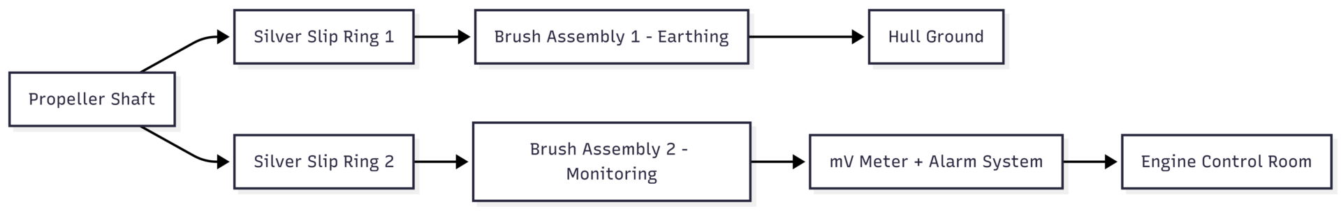
This dual-device arrangement ensures both protection and verification.
Maintenance and Monitoring Best Practices
A well-designed earthing system still requires disciplined maintenance:
- Replace slip rings before the silver layer is worn through.
- Replace brushes at the first sign of wear.
- Keep slip rings clean and dry; corrosion between ring and shaft can be hidden.
- Monthly resistance check (<5 mΩ) if no permanent voltmeter is fitted.
- Monthly verification of monitoring voltmeter readings.
- Overhaul the entire assembly if located in exposed aft positions.
Bearings must be inspected at every overhaul opportunity. Record main bearing top clearance and crankshaft deflection measurements against reference (not maximum) values. Trend data provides far earlier warning than one-off checks against manual limits.
Long-Term Cost and Safety Implications
Unchecked spark erosion leads to unscheduled dry-docking, replacement of multiple main bearings, possible crankshaft reconditioning, and lost revenue from off-hire time. Crankcase explosions carry obvious safety risks to crew. Proper shaft earthing installation and maintenance—costing only a fraction of one bearing set—eliminates this risk entirely.
Marine engineers should treat shaft potential monitoring with the same importance as main engine lube oil analysis or cylinder liner wear measurements. A simple daily glance at the mV-meter, combined with monthly maintenance routines and periodic bearing inspections, prevents catastrophic damage.
By understanding the electrical path from ICCP system through the propeller shaft and into the engine bearings, and by ensuring a dedicated low-resistance earthing route exists at all times, operators can protect their main propulsion engines from spark erosion for the entire service life of the vessel. The technology is proven, the specifications are clear, and the consequences of neglect are too severe to ignore.
Happy Boating!
Share How Spark Erosion Can Damage the Main Propulsion Engine of a Ship? with your friends and leave a comment below with your thoughts.
Read 10 Situations When Ship’s Generator Must be Stopped Immediately until we meet in the next article.