Understanding Hunting Gear Mechanism Of Ships
The steering gear system stands as a critical component in maritime engineering, enabling vessels to maneuver effectively across vast oceans. At its core, this system governs the rudder’s movement, allowing ships to change direction with precision. Among the intricate elements within electro-hydraulic steering gears, the hunting gear mechanism plays a pivotal role as a feedback control system.
It ensures that the rudder achieves and maintains the exact angle commanded from the bridge, preventing oversteering and enhancing operational safety. This article delves deeply into the mechanics, components, and operational principles of the hunting gear, providing a comprehensive understanding for maritime professionals, engineers, and enthusiasts.
The Fundamentals of Ship Steering Gear Systems
Ship steering gear systems are engineered to translate commands from the bridge into physical movements of the rudder, which alters the vessel’s course. The rudder, a large hydrofoil attached to the stern, generates lateral forces when deflected, causing the ship to pivot. The steering gear must amplify small inputs from the helm into substantial torques capable of moving massive rudders against water resistance.
In essence, the system operates on principles of force amplification, similar to how a jack lifts a vehicle with minimal effort. Early ships relied on mechanical linkages, but modern designs predominantly use electro-hydraulic or fully electric systems. Electro-hydraulic systems combine electrical controls with hydraulic power, offering reliability and power efficiency. Fully electric systems, common in contemporary vessels, employ high-voltage motors for direct rudder actuation, providing faster response times and reduced maintenance.
Electro-hydraulic steering gears are categorized into ram-type and vane-type. Ram-type systems use hydraulic cylinders (rams) to push or pull the tiller, while vane-type utilize rotary vanes in a sealed chamber to generate torque. Both types require precise control to avoid oscillations or deviations, which is where the hunting gear integrates seamlessly.
The overall steering gear layout includes four main segments:
- Control Systems: These encompass transmitters, receivers, and interfaces on the bridge where the helmsman inputs commands via wheels, joysticks, or digital screens.
- Powering Units: High-capacity pumps, motors, and electrical supplies that generate the necessary hydraulic pressure or electrical power.
- Transmission Units: Components that convert power into mechanical action, including telemotors and linkages.
- Main Steering Gear: The rudder assembly, tiller, and actuators that execute the turn.
This interconnected framework ensures that even colossal vessels, such as oil tankers displacing hundreds of thousands of tons, can alter course efficiently, even in adverse conditions like high seas.
Evolution and Types of Steering Gear Mechanisms
Historically, steering mechanisms in ships evolved from simple tillers operated by manpower to sophisticated automated systems. In steamships, mechanical advantages were achieved through gears and levers, amplifying human input to move the rudder. The advent of hydraulics revolutionized this, allowing for greater force with less effort.
Today, electro-hydraulic systems dominate due to their balance of power and control. In these, electricity drives pumps that pressurize hydraulic fluid, which then actuates the rudder. The ram-type, for instance, features two or four rams connected to the tiller, providing redundancy for safety. Vane-type systems are more compact, ideal for smaller vessels, and operate by rotating vanes to create differential pressure.
Fully electric steering gears eliminate hydraulics altogether, using servo motors and gearboxes. These are prevalent in advanced ships, offering precise digital control and integration with autopilot systems. However, electro-hydraulic remains standard for many commercial vessels due to proven durability.
Key specifications for typical steering gears include:
| Component | Specification | Typical Range |
|---|---|---|
| Hydraulic Pump Capacity | Flow rate and pressure | 100-500 L/min at 100-200 bar |
| Rudder Torque | Maximum output | 50-5000 kNm depending on ship size |
| Response Time | Time to full rudder deflection | 28-35 seconds for 35° port to starboard |
| Power Supply | Voltage and type | 440V AC, 3-phase for motors |
| Redundancy | Backup systems | Dual pumps and emergency steering |
Prices for steering gear systems vary widely based on vessel size and type. A basic electro-hydraulic setup for a mid-sized cargo ship might cost $500,000 to $1,500,000, while fully electric systems for large tankers can exceed $3,000,000, including installation.
The Role and Necessity of the Hunting Gear Mechanism
The hunting gear mechanism is a specialized feedback loop within electro-hydraulic steering systems, distinct from any literal “hunting” activity. It addresses a fundamental challenge: ensuring the rudder stops exactly at the commanded angle without overshooting or continuous adjustment.
Without such a mechanism, the system might oscillate or “hunt” around the target position, leading to instability. In ships, where precise heading is crucial for navigation, collision avoidance, and fuel efficiency, this feedback is indispensable. It operates by relaying the rudder’s actual position back to the control elements, neutralizing the hydraulic pump once the desired deflection is reached.
Consider a scenario where a vessel needs to turn 30 degrees to starboard. The bridge command activates the system, but without feedback, the rudder might continue moving, causing excessive turn. The hunting gear prevents this by monitoring and correcting in real-time.
In dynamic sea conditions, waves and currents can disturb the rudder angle. The hunting gear acts as a stabilizer, detecting deviations and initiating corrective actions to restore the set position. This reciprocal function ensures continuous alignment, enhancing vessel stability.
Physically, the mechanism leverages Newton’s third law: the reaction force from the rudder’s movement triggers the feedback. While modern ships incorporate digital sensors and automation, the core principle remains mechanical in many designs.
Key Components of the Hunting Gear Mechanism
The hunting gear comprises several interconnected elements that form a closed-loop control system. Central to this is the floating lever, a pivotal rod that integrates inputs and feedbacks.
- Floating Lever: A central linkage with three connection points. One end links to the telemotor receiver (command input), the middle to the pump control rod, and the other to the hunting lever (feedback from rudder).
- Telemotor Receiver: Part of the transmission unit, it translates electrical signals from the bridge into mechanical movement, shifting one end of the floating lever.
- Pump Control Rod (Servo Lever): Controls the variable displacement pump’s stroke. In neutral position (denoted as B), the pump delivers no oil, halting movement.
- Hunting Lever (Feedback Link): Directly attached to the rudder stock or tiller. As the rudder rotates, this lever moves, adjusting the floating lever to return the system to neutral.
- Variable Displacement Pump: The heart of hydraulic power, it adjusts oil flow based on the control rod’s position, driving the rams or vanes.
- Telemotor System: An electro-hydraulic intermediary that conveys commands from bridge to steering compartment via cables and pipes.
These components work in harmony, with the hunting gear ensuring synchronization. For visualization, the following diagram illustrates the schematic flow:
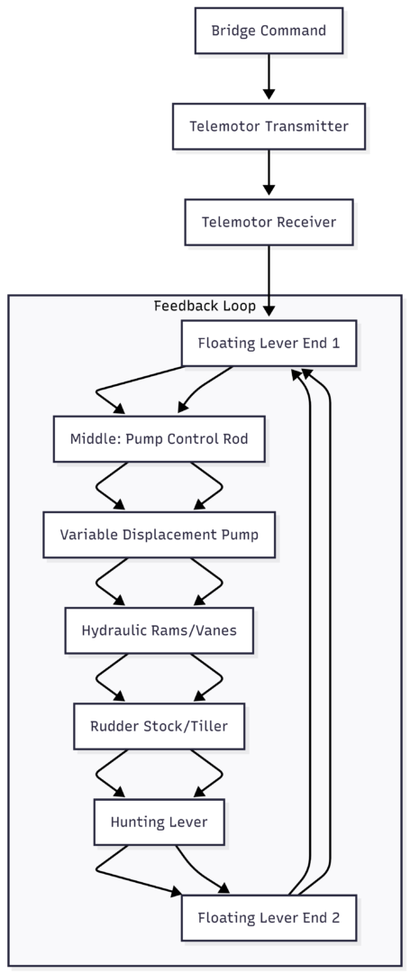
This diagram shows the closed-loop nature, where feedback from the rudder (H to J) neutralizes the pump (E to F).
Working Principle and Operational Sequence
The operational sequence of the hunting gear unfolds in a precise, step-by-step manner, ensuring accurate rudder positioning.
- Command Initiation: The helmsman inputs a turn via the steering wheel or control. This signal travels through the telemotor transmitter to the receiver, moving one end of the floating lever from neutral (A) to a deflected position (A1 for port or A2 for starboard).
- Pump Activation: The floating lever’s movement shifts the pump control rod from neutral (B) to B1 or B2. This strokes the variable displacement pump, discharging pressurized hydraulic oil to the appropriate rams or vanes.
- Rudder Deflection: The hydraulic force acts on the tiller, rotating the rudder toward the commanded angle. For a port turn, oil flows to one set of cylinders, extending rams and pivoting the rudder.
- Feedback Engagement: As the rudder moves, the hunting lever, connected to the rudder stock, shifts from its initial position (C) to C1 or C2. This motion pushes or pulls the other end of the floating lever.
- Neutralization: The hunting lever’s action repositions the floating lever, bringing the pump control rod back to neutral (B). The pump ceases oil discharge, locking the rudder at the exact angle.
- Stabilization and Correction: If external forces like waves alter the rudder angle, the hunting lever detects the change, re-engaging the system to correct it. The process repeats until equilibrium is restored.
For returning to midships, the sequence reverses: the telemotor moves the floating lever oppositely, stroking the pump in the reverse direction until feedback neutralizes it again.
Mathematically, the system’s stability can be modeled using control theory. The rudder angle θ is commanded as θ_c, and the actual angle θ_a is fed back. The error e = θ_c – θ_a drives the pump until e approaches zero. In equation form:
[ e = \theta_c – \theta_a ]
The pump stroke s is proportional to e:
[ s = K \cdot e ]
Where K is the gain factor. Once θ_a = θ_c, s = 0, stopping the system.
This principle mirrors automotive power steering, where feedback disengages torque once the turn is complete, but scaled for maritime demands.
Purpose and Benefits of the Hunting Gear
The hunting gear’s primary purposes revolve around accuracy, stability, and safety.
- Precision in Maneuvering: It guarantees the rudder aligns exactly with the command, critical for tight maneuvers in ports or congested waters.
- Prevention of Oscillations: By damping feedback, it eliminates “hunting” – unwanted back-and-forth movements that could waste energy or cause wear.
- Load Management: It protects the hydraulic pump from continuous full-load operation when stationary, extending component life.
- Safety Enhancement: In emergencies, it ensures reliable control, complying with international standards like SOLAS (Safety of Life at Sea), which mandate redundant steering systems.
In comparison to manual systems in older vehicles or ships, the hunting gear automates what would otherwise require constant human intervention – impractical for large vessels where even minor errors can lead to navigational hazards.
Integration with Modern Technologies
While traditional hunting gears are mechanical, modern iterations incorporate electronics. Digital sensors replace levers, using encoders on the rudder stock for position feedback. Programmable logic controllers (PLCs) process signals, integrating with GPS and autopilot for autonomous navigation.
In fully electric systems, similar feedback loops use motor encoders and servo drives, eliminating hydraulics. However, electro-hydraulic with hunting gear remains vital for many fleets due to robustness in harsh marine environments.
Specifications for advanced hunting gear components include:
| Component | Material/Tech | Price Range (USD) |
|---|---|---|
| Floating Lever Assembly | Stainless Steel | 5,000 – 15,000 |
| Hunting Lever | Alloy Steel | 2,000 – 8,000 |
| Telemotor System | Electro-Hydraulic | 20,000 – 50,000 |
| Variable Pump | Axial Piston Type | 50,000 – 150,000 |
These costs are for replacement parts; full integration adds labor and testing.
For illustrative purposes, consider this state diagram depicting operational states:
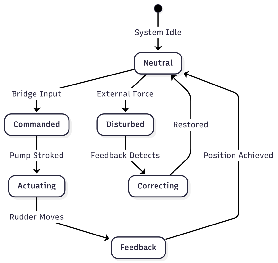
This highlights the cyclical nature of correction.
Practical Applications and Maintenance Considerations
In practice, the hunting gear enables vessels to execute complex maneuvers, such as berthing or evading obstacles. For example, in rough weather, it maintains course by countering wave-induced yaw.
Maintenance involves regular inspections of linkages for wear, hydraulic fluid checks, and alignment verifications. Faults like stuck levers can lead to steering failure, so redundancy – like dual telemotors – is standard.
Training for maritime engineers often includes simulations of hunting gear operations, emphasizing its role in exams and certifications.
Comparison with Related Maritime Systems
To contextualize, compare hunting gear to other vessel components:
- Draft Lines: Markings on the hull for load measurement, unrelated but essential for stability affecting steering.
- Embarkation Ladders: Safety equipment for boarding, not mechanical.
- Seakeeping: Vessel’s ability to maintain performance in waves; hunting gear aids by stabilizing rudder.
- Hull Types: Displacement hulls require more torque, influencing steering gear design.
The hunting gear’s feedback is unique, akin to closed-loop controls in aviation or automotive engineering.
Challenges and Future Developments
Challenges include corrosion in saltwater environments and integration with emerging autonomous technologies. Future developments may see AI-enhanced predictive feedback, reducing response times further.
In electric vessels, hybrid systems blending hunting gear principles with battery-powered actuators are emerging, promising greener operations.
Conclusion
The hunting gear mechanism exemplifies ingenious engineering in ship steering systems, providing essential feedback for precise, safe navigation. By understanding its components, principles, and integration, one appreciates how it transforms simple commands into controlled vessel movements. As maritime technology advances, this mechanism’s foundational role endures, ensuring reliability across global fleets.
Happy Boating!
Share Understanding Hunting Gear Mechanism Of Ships with your friends and leave a comment below with your thoughts.
Read Watertight Doors on Ships: Types, Drills, Maintenance & SOLAS Regulations until we meet in the next article.