Types of Valves Used on Ships: Gate Valve
Gate valves are among the most widely used valves across shipboard piping systems. From engine room cooling lines to ballast tanks and cargo transfer systems, gate valves serve one fundamental purpose: to either allow or completely stop fluid flow. Unlike other valve types used in throttling or flow regulation, a gate valve is a binary device — fully open or fully closed — and that simplicity is precisely what makes it so reliable aboard a vessel.
For any marine engineer, a clear understanding of gate valve construction, types, working principles, and maintenance is not optional. It is essential knowledge for keeping a ship’s systems functional and safe.
What Is a Gate Valve?
A gate valve is a linear-motion valve that controls fluid flow using a flat or wedge-shaped disc — called the “gate” — that moves perpendicular to the direction of flow. When the gate is fully raised, the flow path is completely unobstructed, resulting in minimal pressure drop across the valve. When lowered, it seals against two seats machined into the valve body, completely shutting off flow.
Because the gate sits directly in the flow path when closed and completely clears it when open, gate valves offer a straight-through, full-bore flow with almost zero resistance when fully open. This makes them particularly well-suited for applications where pressure loss must be minimized — a key consideration on ships where long pipework runs are common.
Gate valves cannot and should not be used for throttling. Partial opening causes high-velocity fluid to erode the gate and seat surfaces rapidly, leading to premature failure and leakage.
Construction of a Gate Valve
The gate valve is mechanically straightforward. Its main components are:
| Component | Function |
|---|---|
| Body | Main pressure-containing shell; usually cast iron or steel |
| Gate (Disc) | The closure element; flat, wedge, or parallel slide type |
| Seat Rings | Sealing surfaces inside the body that the gate presses against |
| Stem (Spindle) | Transmits motion from the handwheel to the gate |
| Bonnet | Cover that houses the stem and packing; typically cast iron |
| Handwheel | Manual actuator used to raise or lower the gate |
| Gland Packing | Sealing material around the stem to prevent fluid leakage |
| Yoke / Yoke Nut | Guides and supports the stem; includes the thread engagement |
The body is typically manufactured from cast iron for low-pressure freshwater and seawater applications, bronze for corrosion-sensitive lines, and carbon or stainless steel for high-pressure steam and fuel systems.
How a Gate Valve Works
Operation is simple. Rotating the handwheel turns the stem. The stem, threaded through a nut fixed to the bonnet or yoke, converts rotational motion into linear motion, either raising or lowering the gate.
- Clockwise rotation lowers the gate → valve closes
- Counter-clockwise rotation raises the gate → valve opens
When the gate is fully raised, fluid passes straight through the valve body with virtually no change in direction or velocity. When fully lowered, the gate presses against both seat rings, creating a bidirectional seal that stops flow completely.
Because it requires multiple full turns to open or close, the gate valve is not a quick-action device. This is actually an advantage in critical systems, where accidental operation or sudden flow changes could be dangerous.
Types of Gate Valves Used on Ships
Gate valves are classified primarily by stem design. The two main types used in marine applications are:
1. Rising Stem Gate Valve (Outside Screw and Yoke — OS&Y)
In this design, the threads are on the external portion of the stem, outside the valve body. As the valve is opened, the stem visibly rises above the handwheel. This gives an immediate visual indication of whether the valve is open or closed — a significant safety advantage on ships where quick status checks are critical.
Advantages:
- Visual position indication at a glance
- Stem threads are not exposed to the process fluid, reducing corrosion and wear
- Easier to lubricate and maintain
Disadvantage:
- Requires more vertical clearance; not suitable where headroom is restricted
2. Non-Rising Stem Gate Valve (Inside Screw)
Here, the stem threads engage directly with the gate disc, which is internally threaded. When the handwheel turns, the stem rotates in place while the gate travels up or down along the threads. The stem does not extend upward during operation.
Advantages:
- Compact height; suitable for confined spaces in engine rooms and below-deck compartments
- Simpler external profile
Disadvantages:
- No visual position indicator; requires careful labeling or a position indicator accessory
- Stem threads are exposed to the process fluid, which can cause accelerated wear in corrosive or dirty media
Gate Valve vs. Other Ship Valves: A Comparison
| Valve Type | Primary Use | Flow Control | Pressure Drop | Bidirectional |
|---|---|---|---|---|
| Gate Valve | Isolation (on/off) | On/Off only | Very low (fully open) | Yes |
| Globe Valve | Throttling & regulation | Good throttle | Moderate–high | No |
| Ball Valve | Quick on/off | On/Off | Very low | Yes |
| Butterfly Valve | Isolation & throttling | Moderate | Low | Yes |
| Check Valve | Backflow prevention | Automatic | Low | No |
| Needle Valve | Precise low-flow control | Very precise | High | No |
Gate valves occupy a specific niche: where isolation is the priority, pressure drop must be minimal, and bidirectional flow capability is needed. They are not interchangeable with globe or needle valves in throttling service.
BLEVE — Why Proper Valve Function on Gas Carriers Is Critical
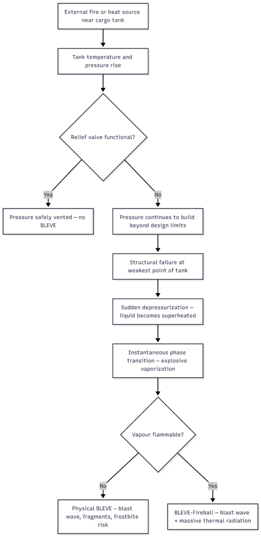
Understanding gate valve maintenance connects directly to preventing catastrophic events on gas carriers, including Boiling Liquid Expanding Vapour Explosion (BLEVE). BLEVE occurs when a pressurized tank containing liquid cargo fails structurally, causing a sudden drop in pressure. This depressurization drops the boiling point of the liquid below its current temperature, triggering instantaneous, violent vaporization.
If the vapour is flammable — as is the case with LPG, propane, or butane — ignition produces a massive fireball and blast wave capable of destroying the vessel and surrounding infrastructure.
A malfunctioning gate valve on a gas carrier’s relief or isolation system can be a contributing factor to overpressurization leading to BLEVE. Relief valves stuck in the closed position due to corrosion, damaged gate seats, or seized stems prevent safe pressure release, allowing internal pressure to build until structural failure occurs.
BLEVE Development Sequence
The minimum temperature at which BLEVE can occur varies by substance:
| Substance | Min BLEVE Temp (°C) | Min BLEVE Temp (°F) |
|---|---|---|
| Methane | −102 | −152 |
| Ethylene | −20 | −4 |
| Propane | 58 | 136 |
| Ammonia | 90 | 194 |
| Chlorine | 102 | 216 |
| n-Butane | 108 | 226 |
| Water | 306 | 583 |
This reinforces why pressure relief valves and isolation gate valves on gas carriers must be maintained in perfect working order.
Common Shipboard Applications of Gate Valves
Gate valves appear throughout a vessel’s piping systems wherever reliable full-bore isolation is required:
- Sea chest and overboard discharge lines — main seawater intake and outlet isolation
- Main bilge suction lines — bilge system isolation in engine rooms
- Ballast tank systems — controlling ballast water filling and discharge
- Fuel oil transfer lines — isolating fuel tanks during transfer operations
- Engine cooling water circuits — isolating pumps and heat exchangers for maintenance
- Cargo handling lines on tankers — product isolation during loading and discharge
- Fire main systems — sectional isolation of the fire main ring
Maintenance and Common Failure Points
Regular maintenance of gate valves is critical. The most common failure modes and their causes are:
| Failure | Cause | Remedy |
|---|---|---|
| Leakage past gate | Worn or corroded seat faces | Re-grind or replace seat rings |
| Leakage past stem | Deteriorated gland packing | Replace packing; tighten gland nut |
| Valve seized / won’t operate | Corrosion of stem threads | Lubricate regularly; exercise valve periodically |
| Gate stuck in partially open position | Debris in seat area | Flush system; inspect gate and body |
| Bonnet leak | Damaged bonnet gasket | Replace gasket during overhaul |
Maintenance schedule recommendations:
- Monthly: Exercise all gate valves (open/close fully) to prevent seizure
- Quarterly: Check gland packing for leakage; tighten or renew as required
- Annual: Inspect seat faces, gate condition, and stem threads during dry-dock or planned maintenance periods
- As required: Renew gland packing and seat rings when wear is evident
Specifications and Typical Costs
Gate valves on ships vary significantly in specification depending on the system they serve:
| Parameter | Bronze (Low Pressure) | Cast Iron | Carbon Steel | Stainless Steel |
|---|---|---|---|---|
| Pressure Rating | PN10–PN16 | PN10–PN16 | PN25–PN40 | PN40–PN100 |
| Temperature Range | Up to 120°C | Up to 120°C | Up to 400°C | Up to 600°C |
| Size Range | 15mm–100mm | 50mm–600mm | 15mm–900mm | 15mm–600mm |
| Typical Use | Domestic, cooling | Ballast, bilge | Steam, fuel | Corrosive media |
| Approx. Cost (DN50) | $30–$80 | $20–$60 | $80–$200 | $150–$500+ |
Marine-grade gate valves must meet classification society approvals (Lloyd’s Register, DNV, Bureau Veritas, etc.) and comply with relevant standards such as ISO 7121 or API 600 for steel gate valves.
Key Takeaways
Gate valves are indispensable on ships — not because they are complex, but because they are reliable, low-resistance isolation devices that handle bidirectional flow across a wide range of fluids and pressures. Their binary open/close function makes them ideal for system isolation while their full-bore design ensures negligible pressure loss in critical seawater, fuel, ballast, and cargo systems.
Understanding their construction, proper operation, and maintenance requirements is fundamental for marine engineers at every level. A seized or leaking gate valve is not a minor inconvenience — in the wrong system, on the wrong ship, it can be a precursor to a far more serious event.
Happy Boating!
Share Types of Valves Used on Ships: Gate Valve with your friends and leave a comment below with your thoughts.
Read How Are Cruise Ships Powered? until we meet in the next article.