Properties Of Membrane Tanks For Transportation Of LNG Cargo On Ships
Liquefied Natural Gas (LNG) has emerged as one of the cleanest and most efficient marine fuels and cargo types in the shipping industry. Transporting LNG at cryogenic temperatures of −160°C requires containment systems engineered to the highest standards of material science, thermal management, and structural integrity. Among all LNG containment systems used on ships, membrane tanks are the most widely adopted — valued for their volumetric efficiency, lightweight design, and proven safety record.
This article covers the complete technical properties of membrane tanks: their design types, material selection, insulation systems, boil-off gas (BOG) management, construction methods, and integrity testing — everything a marine engineer or shipping professional needs to understand.
What Is LNG and Why Does Containment Matter?
LNG is natural gas — primarily methane — that has been cooled to approximately −160°C at atmospheric pressure, condensing it into liquid form. In this state, its volume reduces to about 1/600th of its gaseous equivalent, making it economically viable to transport by sea.
Compared to Compressed Natural Gas (CNG), LNG offers a clear density advantage:
| Property | LNG | CNG |
|---|---|---|
| Temperature | −160°C (atmospheric) | ~30°C (250 bar) |
| Density | ~450 kg/m³ | ~194 kg/m³ |
| Tank Pressure | Near atmospheric | >200 bar |
| Volume for 1000 kg | ~2.2 m³ | ~5.2 m³ |
| Regulatory Complexity | Moderate (cryogenic) | High (high-pressure vessel) |
LNG’s near-atmospheric storage pressure gives it a significant safety and cost advantage over CNG. However, its cryogenic temperature introduces material science challenges that directly shape tank design.
Types of LNG Cargo Containment Systems
There are three primary LNG cargo containment systems used on ships:
- Membrane type — non-self-supporting, integrated into the ship’s hull
- MOSS (Spherical) type — self-supporting spherical tanks on deck
- Prismatic type — self-supporting rectangular tanks
Membrane tanks dominate large-scale LNG carriers because they conform to the shape of the ship’s hull, maximising usable volume and reducing windage compared to the above-deck spherical MOSS design.
What Is a Membrane Tank?
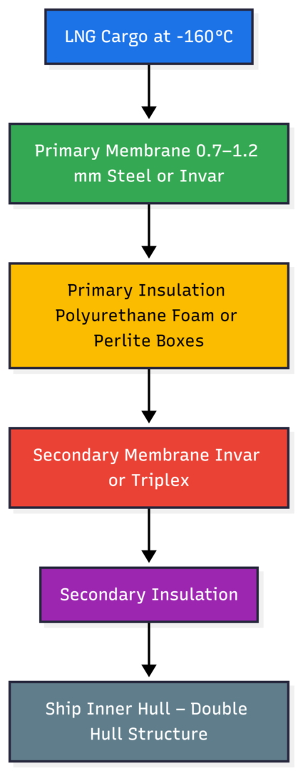
A membrane tank is a non-self-supporting containment system where a thin metallic membrane directly contacts the LNG cargo. The membrane itself does not bear the hydrostatic load — that is transferred through the insulation to the ship’s inner hull structure.
Core Structure (Layer by Layer)
[LNG Cargo]
     ↓
[Primary Membrane] — direct cargo contact (0.7–1.2 mm)
     ↓
[Primary Insulation] — polyurethane foam or perlite-filled plywood
     ↓
[Secondary Membrane] — backup containment barrier
     ↓
[Secondary Insulation]
     ↓
[Ship's Inner Hull (Double Hull)]
This layered barrier system ensures that even if the primary membrane fails, the secondary membrane prevents LNG from reaching the ship’s hull structure.
Diagram: Membrane Tank Cross-Section Layers
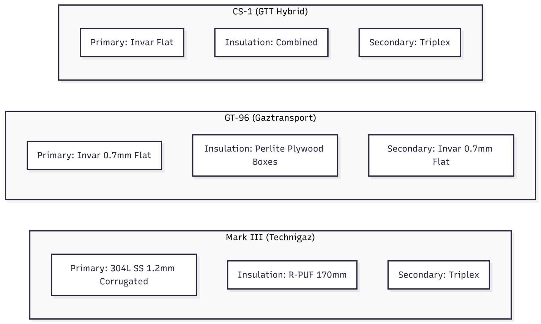
The Three Major Membrane Tank Designs
Two companies — Gaztransport and Technigaz (later merged into GTT) — developed the dominant membrane tank designs. A hybrid design followed.
1. Mark III (Technigaz)
| Feature | Specification |
|---|---|
| Primary Membrane | 304L Stainless Steel, 1.2 mm, corrugated (“waffle” pattern) |
| Secondary Membrane | Triplex (glass wool bonded between two aluminium foil layers) |
| Primary Insulation | Reinforced polyurethane foam (R-PUF), ~170 mm thick |
| Secondary Insulation | R-PUF panels |
| Corrugation Purpose | Accommodates thermal contraction at cryogenic temperatures |
The corrugated surface of the stainless steel membrane is the key innovation of Mark III. When cooled to −160°C, the corrugations contract and flex, preventing structural stress that would otherwise crack a flat sheet.
2. GT-96 (Gaztransport)
| Feature | Specification |
|---|---|
| Primary Membrane | Invar (36% Nickel steel), 0.7 mm flat |
| Secondary Membrane | Invar, 0.7 mm flat |
| Primary Insulation | Plywood boxes filled with Perlite |
| Secondary Insulation | Plywood boxes filled with Perlite |
| Key Advantage | Near-zero thermal expansion — no corrugation needed |
Invar (Fe-36Ni) has a thermal expansion coefficient of approximately 1.2 × 10⁻⁶/°C, compared to ~17 × 10⁻⁶/°C for standard stainless steel. This near-zero expansion eliminates the need for corrugation, allowing flat membranes at just 0.7 mm thickness.
3. CS-1 (GTT — Hybrid Design)
| Feature | Specification |
|---|---|
| Primary Membrane | Invar (flat, low expansion) |
| Secondary Membrane | Triplex (from Mark III) |
| Insulation | Combination approach |
CS-1 combines the primary membrane from GT-96 with the secondary barrier from Mark III, offering design flexibility for specific vessel configurations.
Diagram: Membrane Tank Design Comparison
Material Selection: Why Not Carbon Steel?
The choice of material for LNG membrane tanks is governed primarily by cryogenic behaviour. At −160°C, many materials become dangerously brittle — a phenomenon defined by the Ductile-to-Brittle Transition Temperature (DBTT).
Ductile vs. Brittle Failure
- Ductile materials deform before failing — they give a warning
- Brittle materials fail suddenly without deformation — catastrophic failure (like glass)
For a containment system holding cryogenic LNG, only materials that remain ductile at −160°C are acceptable.
Crystal Structure Determines Behaviour
| Crystal Structure | Examples | DBTT | Behaviour at Cryogenic Temp |
|---|---|---|---|
| Face-Centred Cubic (FCC) | Austenitic SS (304L), Invar | No transition | Remains ductile |
| Body-Centred Cubic (BCC) | Carbon steel, ferritic steel | High (0°C to −50°C) | Becomes brittle |
FCC metals remain ductile at cryogenic temperatures because of their slip system — closely packed atomic planes can slide against each other under stress, allowing plastic deformation rather than fracture. BCC metals are loosely packed and require much higher shear stress to deform, causing brittle fracture before significant deformation occurs.
This is why 304L stainless steel (FCC/austenitic) and Invar (FCC) are used for LNG membranes, while carbon steel is entirely unsuitable.
Heat Transfer and Insulation
The insulation system in a membrane tank serves two critical purposes:
- Preventing heat ingress that would vaporise the LNG
- Managing Boil-Off Gas (BOG) generation within acceptable rates
Heat transfer is governed by Fourier’s Law of Conduction:
Q = k × A × ΔT / t
Where:
- Q = heat transfer rate (W)
- k = thermal conductivity of material (W/m·K)
- A = surface area (m²)
- ΔT = temperature difference (K)
- t = insulation thickness (m)
Increasing insulation thickness (t) directly reduces heat transfer. The insulation thickness in membrane tanks (typically 170–300 mm depending on design) is calculated based on the allowable Boil-Off Rate (BOR) for that vessel.
| Insulation Material | Thermal Conductivity (k) | Used In |
|---|---|---|
| Reinforced Polyurethane Foam (R-PUF) | ~0.024 W/m·K | Mark III, CS-1 |
| Perlite (in plywood boxes) | ~0.045 W/m·K | GT-96 |
| Triplex (secondary barrier) | ~0.040 W/m·K | Mark III secondary |
Boil-Off Gas (BOG): Causes and Management
LNG is highly volatile. Even with insulation, some heat ingress inevitably causes vaporisation — this is Boil-Off Gas (BOG). Managing BOG is critical both for cargo economics (loss of product) and tank safety (pressure build-up).
Primary Causes of BOG
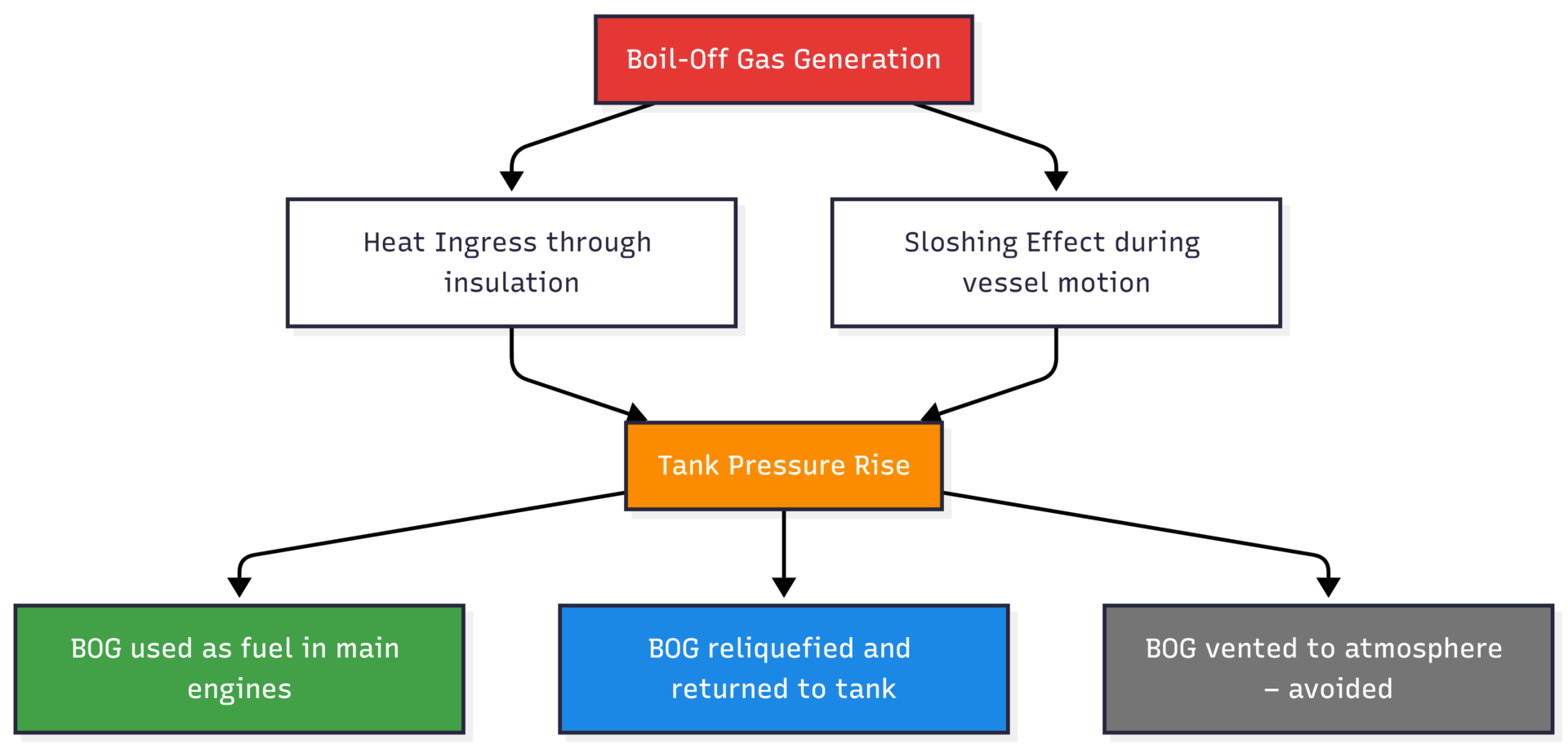
Modern LNG carriers route BOG to the main engines as fuel (dual-fuel engines), effectively converting an unavoidable by-product into propulsion energy. This is one of the economic advantages of LNG shipping — fuel costs partially offset cargo losses.
LNG Tank Construction: Welding and Standards
Membrane tank construction requires precision welding. The two primary techniques used are:
- TIG Welding (Tungsten Inert Gas) — high precision, slower speed
- Plasma Welding — slightly faster than TIG, better productivity for large areas
The quality of every weld seam is critical given the cryogenic service conditions.
Welding Acceptance Criteria (per ABS Class)
| Parameter | Acceptable Value |
|---|---|
| Width of weld seam | 3 mm ≤ width ≤ 4.8 mm |
| Gap before welding | ≤ 0.3 mm |
| Oxidation (flat part) | ≤ 10 mm |
| Oxidation (corrugation) | ≤ 20 mm |
| Weld throat | > 0.8 mm |
| Tack weld pitch (ABS) | 50–70 mm |
Key Welding Notes
- 1.2 mm membrane sheets are welded to 8 mm steel corners — preliminary tack welding positions the sheet before full continuous welding
- Fixation rivets are aluminium — no welding is permitted on these, as aluminium dilution causes fracture risk
- Triplex bonding (secondary barrier tightness) uses epoxy glue at 520 g/m²
- Panel-to-hull bonding uses Epoxy Mastic (resin + hardener), whose elastic behaviour compensates for local hull deflection
Tank Integrity Testing
Two critical tests verify membrane tank integrity before a vessel enters service.
1. Helium Leak Test (Primary Membrane)
Helium is introduced into the insulation layer under pressure. A vacuum hood is placed over each weld seam, drawing out any leaking helium. The helium detector translates ion signal strength into a precise leak rate. Helium is used because its small atomic size makes it the most sensitive leak detection medium.
2. Secondary Barrier Tightness Test (Vacuum Decay Test)
This test verifies the secondary membrane’s integrity over time.
- The primary space is maintained at atmospheric pressure
- The secondary space is subjected to approximately −500 mbar vacuum
- Pressure rise is monitored over 12 hours
- A vacuum decay curve is plotted
Integrity Evaluation — Normalised Porosity Area (NPA):
NPA = (1.210 × 10⁻³ × V_IS) / (A_SB × Δt)
Where:
- A_SB = secondary barrier surface area
- V_IS = volume of secondary barrier insulation space
- Δt = time taken for pressure to rise from −400 mbar to −300 mbar
Acceptance criterion: NPA ≤ 0.85 cm²
Safety Systems in Membrane Tank Operation
| Safety Feature | Purpose |
|---|---|
| Nitrogen inert gas in insulation space | Prevents flammable mixture in interbarrier space |
| Continuous leak detection between membranes | Early warning of primary membrane failure |
| Pressure relief valves | Prevents over-pressurisation from BOG build-up |
| Double hull integration | Secondary structural protection |
| BOG management system | Controls tank pressure and prevents venting |
Membrane Tanks vs. MOSS Spherical Tanks
| Parameter | Membrane Tank | MOSS (Spherical) |
|---|---|---|
| Self-supporting | No | Yes |
| Hull integration | Full | Partial (above deck) |
| Volume utilisation | High (~98% of hull) | Lower (spheres waste corners) |
| Windage | Low | High (exposed spheres) |
| Maintenance access | Complex | Easier |
| Sloshing sensitivity | Higher | Lower |
| Common vessel size | 125,000–180,000 m³+ | 125,000–145,000 m³ |
The rectangular geometry of membrane tanks allows them to fill virtually the entire hull cross-section, making them the preferred choice for Q-Flex and Q-Max class LNG carriers exceeding 200,000 m³ capacity.
Conclusion
Membrane tanks represent the engineering pinnacle of cryogenic cargo containment for LNG shipping. Their design — thin FCC-structured metallic membranes, multi-layer insulation barriers, precision-welded construction, and rigorous integrity testing — directly addresses every challenge posed by LNG’s cryogenic and volatile nature.
The choice between Mark III, GT-96, and CS-1 designs depends on vessel specifications, insulation performance requirements, and allowable BOG rates. What all three share is the fundamental principle: transfer the structural load to the ship’s hull, keep the membrane thin and flexible, and maintain absolute cargo containment through redundant barriers and continuous monitoring.
For marine engineers, naval architects, and LNG shipping professionals, understanding these properties is essential — not just for safe operation, but for optimising cargo economics across the entire voyage.
Happy Boating!
Share Properties Of Membrane Tanks For Transportation Of LNG Cargo On Ships with your friends and leave a comment below with your thoughts.
Read 8 Common Problems of Ship’s Incinerator Mariners Should Know until we meet in the next article.