Overview Of Sludge And Bilge Management Onboard Ships
Every operating ship produces two categories of oily waste that must be managed carefully: sludge — the heavy residue generated by fuel and lubricating oil systems — and bilge water — the oily liquid that accumulates at the lowest points of the engine room. Both represent environmental hazards if mishandled and legal liabilities if records are not kept accurately. MARPOL Annex I, the international treaty governing oil pollution from ships, imposes strict requirements on how these wastes are stored, treated, and disposed of. Violations carry fines that can exceed $1 million USD and may result in vessel detention and criminal prosecution of officers.
This guide covers where sludge and bilge water come from, how they are stored and processed onboard, what equipment is involved, and what the regulatory framework requires.
What Is Sludge and Where Does It Come From?
Sludge is the collective term for oily residues separated from fuel oil and lubricating oil during purification, as well as residues draining from engine components and machinery trays. It is a high-viscosity waste that cannot be pumped without heating and cannot be discharged overboard under any circumstances.
Primary Sludge Sources
Fuel oil purifiers separate water and particulate matter from heavy fuel oil (HFO) before it enters the settling and service tanks. The purifier bowl discharges automatically at set intervals — typically every 30 to 90 minutes depending on fuel quality — into a dedicated HFO purifier sludge tank. The volume of sludge generated here is directly related to fuel quality: higher water and sediment content in the bunker fuel means more frequent and larger discharges.
Lubricating oil purifiers similarly separate water and contaminants from the main engine and generator lubricating oil systems. Discharge intervals are set based on running hours and oil analysis results. The sludge from lube oil purifiers is collected into a separate LO purifier sludge tank on most vessels.
Main engine scavenge drains collect cylinder lubricating oil scraped from the liner surfaces as pistons reciprocate. This oil accumulates in the scavenge spaces between units and drains through dedicated lines into a scavenge drain tank or the common sludge tank. Scavenge drain sludge typically contains a mixture of cylinder oil, carbon deposits, and water.
Main engine stuffing box drains collect crankcase oil scraped from the piston rod as it passes through the stuffing box. Each unit has a drain line that delivers this residue to a dedicated stuffing box drain tank. Contamination of this stream with seawater can indicate a defective stuffing box seal and requires investigation.
Save-all trays and machinery drips beneath fuel oil pumps, filters, purifiers, heaters, and other oil-handling equipment collect any minor leakage. These trays drain to the sludge tank. In a well-maintained engine room, volumes from this source should be small.
Miscellaneous drains — air bottle drain traps, HFO settling and service tank water drain outlets, and various system low-points — also feed into sludge tanks. These contribute oily water that must be evaporated before incineration.
As a general benchmark, average sludge generation is considered to be approximately 1.5% of total fuel consumed. Consistent sludge production above this figure indicates purifier inefficiency, excessive fuel water content, or abnormal engine wear and warrants investigation.
Sludge Tank Arrangements
The number and configuration of sludge tanks varies between vessels depending on shipyard design and installed machinery. Some ships have one large common sludge tank; others have individual tanks for each source — HFO purifier sludge, LO purifier sludge, scavenge drains, and stuffing box drains — plus a waste oil (incinerator feed) tank.
All sludge tanks must be listed in the vessel’s International Oil Pollution Prevention (IOPP) Certificate. Every transfer into or out of an IOPP-designated tank must be recorded in the Oil Record Book Part I (Engine Room), signed by the Chief Engineer. Inaccurate or incomplete records are among the most common causes of port state control (PSC) deficiencies and prosecutions.
| Tank | Function | Typical Capacity |
|---|---|---|
| HFO purifier sludge tank | Receives purifier bowl discharges from FO purifiers | 2–10 m³ |
| LO purifier sludge tank | Receives purifier bowl discharges from LO purifiers | 1–5 m³ |
| Scavenge drain tank | Collects ME scavenge space oil drains | 1–4 m³ |
| Stuffing box drain tank | Collects piston rod scraper box oil | 0.5–2 m³ |
| Common sludge tank | Consolidates all sources on some vessels | 5–20 m³ |
| Waste oil (incinerator feed) tank | Heated holding tank; feeds the incinerator | 3–10 m³ |
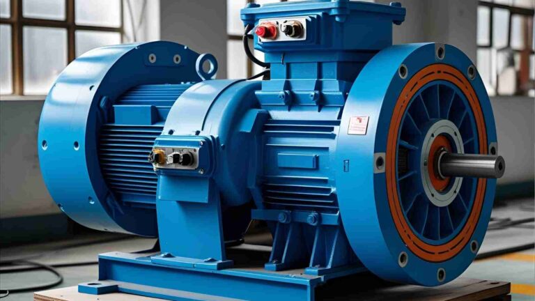
Sludge pumps — gear-type or progressive-cavity positive displacement pumps capable of handling high-viscosity fluids — are used for all sludge transfers. Steam tracing on the suction and discharge lines is essential to keep viscous sludge mobile at all times.
Sludge Treatment: Evaporation and Incineration
Sludge collected from purifiers and tank drains contains a significant proportion of water. Before it can be burned in the incinerator, this water must be evaporated. Burning sludge with high water content causes incomplete combustion, burner flameouts, and excessive smoke — all of which create operational and regulatory problems.
Evaporation Process
Sludge from the various source tanks is transferred to the waste oil tank, which is equipped with steam heating coils. Steam valves (supply and return) are opened, and the tank temperature is raised to 100°C. At this point, water begins to evaporate from the sludge. When the temperature climbs above 100°C, it indicates that the free water has been driven off and the remaining material is oil. The sludge is now ready for incineration.
On ships with a common sludge tank rather than multiple individual tanks, water is allowed to settle to the bottom of the tank over several days. Suction is then taken from the bottom of the tank to transfer settled water to the waste oil tank for evaporation. The temperature of the waste oil tank must be below 90°C before receiving new sludge to prevent a rapid boil-off that could cause dangerous pressure build-up.
The volume of water evaporated from the waste oil tank must be recorded in the Oil Record Book.
Incineration Process
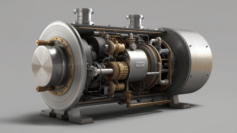
Marine incinerators approved under IMO Resolution MEPC.244(66) are capable of burning waste oil, sludge, garbage, and other onboard waste. A typical shipboard waste oil incinerator has a thermal capacity of 50,000 to 1,500,000 kcal/hr depending on vessel size, and can reduce sludge volume by 95% or more.
The incineration procedure follows this general sequence:
- Drain and visually check the waste oil tank for free water before starting.
- If fitted, activate the tank agitator to homogenise the sludge for consistent atomisation.
- Warm up the incinerator on diesel oil until the furnace reaches operating temperature.
- Open the waste oil feed valve. Confirm that steam tracing on the waste oil line is functional and strainers are clear.
- Adjust damper and atomising pressure per the manufacturer’s manual.
- Monitor and log incinerator operating parameters (chamber temperature, furnace pressure, flue gas temperature).
- Record the total volume of waste oil incinerated in the Oil Record Book.
Engine Room Bilge Water: Sources and Collection
Bilge water is the oily water mixture that accumulates in the bilge wells at the lowest points of the engine room. It originates from:
- Leakages from seawater and freshwater pump shaft seals
- Leakages from cooler connections and expansion joints
- Minor spills during maintenance and fuel handling
- Condensate from steam systems
- Air cooler condensate (discussed separately below)
Bilge wells are located at the forward tank top (port and starboard), the aft recess under the flywheel, and in the shaft tunnel where fitted. All bilge wells drain into these low-points by gravity. The oily bilge pump (centrifugal or diaphragm type) transfers bilge water from the wells to the bilge holding tank via a bilge primary tank.
Bilge Tank Hierarchy
| Tank | Purpose |
|---|---|
| Bilge primary tank | Gravity separation of oil from bilge water; oil skimmed from surface |
| Bilge holding tank | Main storage for engine room bilge water pending OWS treatment or shore discharge |
| Air cooler drain tank | Receives condensate from ME and generator scavenge air coolers |
| Bilge evaporation tank | Present on some vessels; allows heating and evaporation of oily bilge water |
The air cooler drain tank deserves specific mention. When ambient air is compressed by the turbocharger and cooled in the scavenge air cooler, moisture in the air condenses to liquid water. This water collects in drain traps below the coolers and drains to the air cooler drain tank. Because engine room air often contains oil vapour, this condensate may have measurable oil content. It is discharged overboard through a dedicated pump fitted with an oil content monitor (OCM), or transferred to the bilge holding tank for OWS processing.
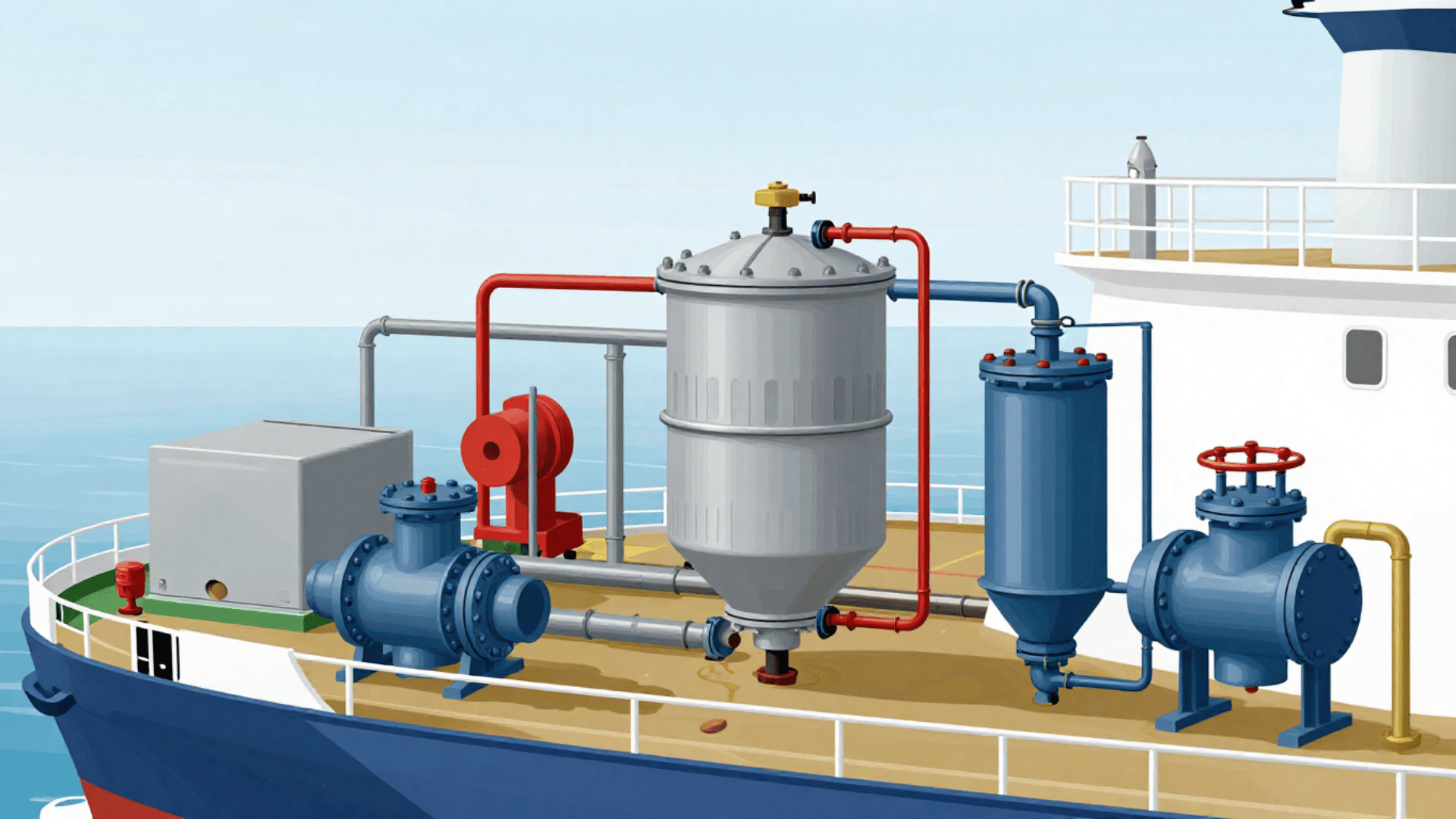
Oily Water Separator (OWS): Operation and Standards
The Oily Water Separator (OWS) is the primary treatment equipment for engine room bilge water. MARPOL Annex I Regulation 14 prohibits the overboard discharge of bilge water with an oil content exceeding 15 parts per million (ppm) — measured after the separator — anywhere in the sea (except in special areas and Arctic waters, where stricter or zero-discharge rules apply). An Oil Content Monitor (OCM) must be fitted in the discharge line and must automatically close the overboard valve and redirect flow back to the holding tank if the 15 ppm threshold is exceeded.
MEPC.107(49) specifies the performance and testing standards for OWS equipment installed on vessels of 400 GT or more. Equipment must be type-approved and regularly calibrated — the OCM sensor typically requires calibration every 12 months to remain within regulatory compliance.
OWS Operating Principle
Most shipboard OWS systems operate in two or three stages:
- Gravity separation: Coarse separation of oil and solids from water using density difference in a settling chamber.
- Coalescing separation: Water passes through coalescing media (polypropylene plates or fibres) where fine oil droplets merge into larger droplets that rise to an oil collection space.
- Membrane or adsorption polishing (tertiary stage): Present on advanced units; further reduces residual oil content well below the 15 ppm limit.
The separated oil accumulates in a collection chamber and is periodically drained back to the bilge holding tank or sludge tank — never overboard. Clean water passing the OCM verification is discharged overboard only when the vessel is underway at sea (not in port or in a special area).
Every OWS discharge operation must be recorded in the Oil Record Book, including the vessel’s position at start and end of discharge, the time and duration of operation, and the volume discharged.
MARPOL Annex I: Regulatory Framework
MARPOL Annex I is the binding international regulation governing the prevention of oil pollution from ships. Its key requirements relevant to sludge and bilge management are summarised below.
| Requirement | Detail |
|---|---|
| Bilge water discharge limit | Maximum 15 ppm oil content; zero in special areas |
| OWS mandatory for | Vessels of 400 GT or more |
| Oil Record Book Part I | Must record all transfers, discharges, and incineration; must be retained onboard for 3 years |
| IOPP Certificate | Must list all designated sludge and bilge tanks |
| Shore reception facility use | Must be recorded in ORB; port must provide adequate reception facilities |
| Sludge discharge overboard | Prohibited under all circumstances |
| Special areas | Stricter limits apply in Mediterranean, Baltic, Black Sea, Red Sea, Gulfs, Gulf of Aden, Antarctic, and NW European Waters |
Non-compliance penalties under US law (as an example of enforcement severity) include fines of up to $25,000 per day of violation and potential imprisonment of responsible officers. In the United States, the Act to Prevent Pollution from Ships (APPS) has resulted in multi-million dollar fines against shipping companies and criminal convictions of Chief Engineers who falsified Oil Record Books — commonly referred to as “magic pipe” cases, where a bypass hose was used to discharge bilge water directly overboard without OWS treatment.
Cargo Hold Bilge Water
Container vessels and general cargo ships have bilge wells at the bottom of each cargo hold, typically port and starboard. Cargo hold bilges generally contain only rainwater and seawater ingress, with no oil contamination under normal circumstances. They are typically discharged overboard via a bilge eductor driven by the fire and general service (F&GS) pump while the vessel is at sea.
However, a visual inspection of hold bilge wells is mandatory before any overboard pumping. If oil traces are found — from cargo spillage, lubricant leaks from cargo equipment, or other contamination — the bilge water must be directed to the bilge holding tank or another designated engine room tank and processed through the OWS before discharge.
Hold bilge wells are also connected to bow thruster room bilges, pipe duct bilges, chain locker bilges, and forepeak void spaces. Remote-operated valves for these connections are typically controlled from the ship’s office or engine control room.
Sludge Reduction Technology
For vessels seeking to reduce the volume of sludge requiring shore discharge or incineration, onboard centrifugal sludge-processing units offer a practical solution. Systems such as the Mitsubishi Sludge Buster use high-speed centrifugal separation to extract recoverable fuel oil from sludge, returning it to the HFO service system for combustion. The residual dry cake is significantly reduced in volume and easier to incinerate.
The economic case is clear: heavy fuel oil recovered from sludge that would otherwise be incinerated or discharged ashore represents direct fuel savings. At a bunker cost of $500–$700 per tonne, recovery of even 1–2 tonnes per voyage adds up significantly over a vessel’s trading life.
Maintenance and Best Practices
OWS and Incinerator Maintenance
| Equipment | Maintenance Task | Frequency |
|---|---|---|
| OWS coalescing media | Clean or replace | Per manufacturer / condition |
| OCM sensor | Calibration | Every 12 months minimum |
| OWS strainers | Clean | Monthly or as required |
| Incinerator refractory lining | Inspect for cracks | Each opening |
| Incinerator burner nozzles | Clean and inspect | Monthly |
| Waste oil tank heating coils | Pressure test | Annual or dry dock |
| Sludge pump strainers | Clean | Weekly |
Oil Record Book Discipline
The ORB is the single most scrutinised document during PSC inspections. Common deficiencies include missing entries for small transfers, incorrect dates or volumes, entries that don’t match the IOPP tank list, and failure to record the vessel’s position during OWS overboard discharge. Every Chief Engineer should:
- Record all transfers the same day they occur — not retroactively
- Cross-check cumulative sludge generated against fuel consumption (approximately 1.5% ratio)
- Ensure all shore reception facility receipts are retained onboard
- Never leave blank lines in the ORB; strike through any unused code lines
Summary
Sludge and bilge management sits at the intersection of environmental compliance, operational efficiency, and crew safety. The consequences of mismanagement — from blocked purifiers and clogged strainers at the operational level to multi-million dollar fines and criminal prosecution at the regulatory level — make this one of the most important areas of engine room administration.
The key principles are straightforward: understand where waste is generated, store it in designated tanks, treat it correctly using approved equipment, record every transfer and discharge accurately in the Oil Record Book, and never discharge untreated oily waste overboard. Technologies like modern OWS systems, real-time oil content monitors, and onboard sludge reduction centrifuges make MARPOL compliance achievable without excessive shore disposal costs. The Chief Engineer’s signature in the Oil Record Book is both a professional responsibility and a legal obligation — and PSC inspectors know exactly what to look for.
Happy Boating!
Share Overview Of Sludge And Bilge Management Onboard Ships with your friends and leave a comment below with your thoughts.
Read Applications of Water Mist Systems on Passenger Ships until we meet in the next article.