Interpreting an Oil Analysis Report – The Top 10 Tips
Every time a ship takes on bunkers, four samples are collected at the manifold: one for the supplier, one for MARPOL retention, one kept aboard, and one dispatched to a shore laboratory. That fourth sample is the one that matters most for engine room decision-making. When the report comes back — usually within three to four days — it contains a dense matrix of numbers that can mean the difference between a trouble-free passage and a costly engine breakdown at sea.
Yet many junior engineers glance only at density and viscosity, adjust the purifier gravity disc, and file the rest away. That habit leaves a significant amount of actionable intelligence on the table. A fuel oil lab analysis is one of the most powerful tools available to a marine engineer. Used properly, it tells you exactly how to handle the fuel, what wear risks it carries, and whether it complies with the regulations governing the waters you sail through.
This guide breaks down the ten parameters that demand your full attention every single time a report lands in your inbox — along with the practical steps to take based on what you find.
Why Fuel Oil Lab Analysis Matters
Ships typically burn heavy fuel oil (HFO, also called Bunker C or RMG/RMK grades), a residual product at the bottom of the refinery process. It is thick, corrosive, laden with trace metals, and varies significantly from one bunker port to the next. The Bunker Delivery Note (BDN) your supplier hands over gives a rough density figure used to calculate the mass of fuel delivered — it is not a precision quality document.
The lab report is. Cross-referencing your report against the BDN is the first sanity check: if the density or viscosity deviates sharply from what was ordered, you have grounds to raise a formal protest and flag the issue to your technical superintendent.
Beyond compliance, the report guides every downstream decision: which gravity disc to fit in the purifier, what temperature to maintain in settling and service tanks, how aggressively to heat the bunker tanks, how quickly to expect your backwash filters to choke, and whether you are carrying fuel that will quietly destroy your cylinder liners over the next few weeks.
The 10 Parameters to Check — A Reference Table
| # | Parameter | ISO 8217 Limit (RMG 380) | Key Risk if Out of Range |
|---|---|---|---|
| 1 | Density at 15°C | Max 991 kg/m³ | Incorrect gravity disc → poor purification |
| 2 | Viscosity at 50°C | 380 cSt max | Wrong heating temp → poor atomisation |
| 3 | Water Content | Max 0.5% v/v | Fuel pump seizure, combustion instability |
| 4 | Flash Point | Min 60°C (SOLAS) | Fire and explosion risk |
| 5 | Sulfur Content | ≤0.50% global; ≤0.10% ECA | MARPOL Annex VI non-compliance |
| 6 | Aluminum + Silicon (Cat Fines) | Max 60 mg/kg | Abrasive wear on liners and pumps |
| 7 | CCAI | Max 870 (guideline) | Ignition delay, engine damage |
| 8 | Pour Point | Reported | Fuel handling failure in cold regions |
| 9 | Vanadium & Sodium | V: max 350 mg/kg | High-temperature corrosion of exhaust valves |
| 10 | Ash Content / Compatibility | Max 0.10% m/m | Deposits, sludge, incompatible mixing |
Tip 1 — Density: More Than a Billing Number
Density at 15°C appears on the BDN primarily so the supplier can calculate the tonnes of fuel delivered. But that figure is rounded and sometimes estimated. Your lab-measured density is the accurate value you need for two things.
Gravity disc selection: Older centrifugal purifiers (Alfa Laval, Mitsubishi, Westfalia) use a gravity disc whose inner diameter is sized to create a water-fuel interface at the correct radius inside the bowl. Select a disc that is too large for your fuel density and water — along with the sludge it carries — will overflow into the clean oil side. Most manufacturers provide a disc selection chart; use the lab density, not the BDN figure.
Density trend across batches: If density creeps above 991 kg/m³, you are approaching the limit at which standard purifiers lose effectiveness entirely. Flag this to the office and consider blending or additional treatment.
Tip 2 — Viscosity: The Temperature Map for Your Fuel System
HFO grades are defined by their kinematic viscosity at 50°C — 380 cSt for RMG 380, 180 cSt for IFO 180. Neither figure is useful at the injector; you need the fuel arriving at approximately 13–15 cSt for correct atomisation and combustion.
Most modern ships have an automated viscotherm that reads viscosity in the fuel line and adjusts steam heating accordingly. On older vessels with manual temperature regulation, the lab report is essential: laboratories typically supply a viscosity-temperature curve alongside the numerical result. Read the temperature at which your specific batch reaches 13–15 cSt and set your service tank heating accordingly.
A deviation from expected viscosity also tells you when fuel has been adulterated. Unusually low viscosity may indicate blending with distillate to inflate volume; unusually high viscosity means your heating system will be working harder than normal throughout the voyage.
Tip 3 — Water Content: The Hidden Saboteur
Water in fuel oil reduces calorific value, promotes microbial growth during long storage, and — most critically — causes hydraulic lock and seizure in fuel injection pumps. The ISO 8217 limit for residual fuels is 0.5% v/v; anything above this should prompt immediate action.
Practical response protocol:
- Begin heating the bunker tank immediately after bunkering to encourage water to settle and stratify
- Drain settling tank sludge frequently — expect sludge tanks to fill faster than normal
- Monitor purifier sludge discharge intervals; high water means more frequent automatic desludging
- On long storage legs, check for microbial contamination (black sludge, sulfurous odour) which can block filters completely
Water that has emulsified into the fuel rather than settling freely is harder to remove and requires extended purifier run times at reduced throughput.
Tip 4 — Flash Point: A SOLAS Red Line
SOLAS Chapter II-2 is unambiguous: no fuel oil used in machinery spaces shall have a flash point below 60°C. This is not a guideline — it is a legal requirement. If your lab report shows a flash point below 60°C, do not use that fuel until the issue is investigated and formally resolved with your technical superintendent and flag state if necessary.
Low flash point in residual fuel almost always indicates contamination with lighter products, most commonly distillate or naphtha mixed in during blending or loading operations. Port state control inspectors can and do check bunkering records against lab reports.
Tip 5 — Sulfur Content: MARPOL Compliance and Cold Corrosion
Sulfur content governs two entirely different concerns.
Regulatory compliance: Under MARPOL Annex VI, the global sulfur cap is 0.50% m/m. Inside Emission Control Areas (ECAs — including the North Sea, Baltic, North American coasts, and US Caribbean), the limit drops to 0.10% m/m. Before entering an ECA, verify your lab result or confirm your switch to MGO/VLSFO. Non-compliance carries significant port state control penalties and can result in vessel detention.
Cold corrosion management: Sulfur oxides formed during combustion combine with moisture to produce sulfuric acid on cooled cylinder surfaces. High-sulfur fuels require higher jacket cooling water temperatures — especially during slow steaming or port maneuvering — to keep liner temperatures above the acid dew point. Modern intelligent engines (MAN B&W ME series, Wärtsilä RT-flex) automatically adjust cylinder oil feed rates based on the sulfur content in the fuel management system; your lab-confirmed sulfur value should be entered into that system.
Tip 6 — Aluminum + Silicon (Cat Fines): The Abrasion Threat
Catalytic cracking in modern refineries uses aluminum silicate catalyst particles. Some always carry over into the residual fuel product. These particles — known universally as cat fines — are harder than the steel surfaces inside your fuel pumps and cylinder liners. Even at concentrations within the ISO 8217 limit of 60 mg/kg, they cause measurable abrasive wear. Above that limit, the damage accelerates rapidly.
What high cat fines mean operationally:
- Reduce purifier throughput to maximum possible retention time in the centrifuge bowl — this is the primary removal mechanism
- Expect your automatic backwash filter to choke more frequently; never bypass it
- If your vessel has a history of high cat-fine bunkers, consider an annual drain and physical clean of the fuel oil service tank where settled particles accumulate
- Monitor fuel pump plunger and barrel clearances more frequently during the voyage
The combination of aluminum and silicon (Al + Si) is reported together because both are present in the catalyst. A value of Al + Si above 80 mg/kg in the delivered sample warrants a formal complaint to the supplier and possible refusal of the bunker.
Tip 7 — CCAI: Predicting Combustion Quality
The Calculated Carbon Aromaticity Index is not measured directly — it is calculated from density and viscosity. It is the industry’s proxy for ignition quality in residual fuels.
CCAI = Density(15°C) – 141 log[log(Viscosity(50°C) + 0.85)] – 81
The generally accepted threshold is 870. Fuels with CCAI above 870 have poor ignition quality — the spray of atomised fuel ignites later than the engine design expects, producing ignition delay. The consequences range from rough running and misfires to severe mechanical stress from late, high-pressure combustion.
Operating guidance for high-CCAI fuel:
- Avoid prolonged low-load operation; run the engine at higher loads periodically to burn off deposits
- Monitor exhaust temperatures for individual cylinders to detect misfiring units early
- Discuss with your superintendent whether combustion improver additives are justified for the batch
Tip 8 — Pour Point: Cold Region Fuel Handling
Pour point is the lowest temperature at which the fuel remains fluid enough to flow. It sounds straightforward, but the implications reach into your bunker tank heating strategy for an entire voyage.
If your vessel is transiting cold-water regions — northern European waters, the North Pacific in winter, polar routes — and your bunker tank heating is insufficient to keep fuel above its pour point, you will be unable to transfer fuel to the settling tank. The fuel effectively solidifies in the tank.
The practical rule: maintain bunker tank temperature at least 10°C above the measured pour point at all times. For VLSFO blends, pour points can vary widely depending on the blend components, making the lab value particularly important — do not rely on grade assumptions.
Tip 9 — Vanadium, Sodium, and High-Temperature Corrosion
Vanadium is a naturally occurring element in crude oil that concentrates in residual fractions. Sodium typically enters fuel through seawater contamination during loading or storage. Individually, each causes problems. Together, they are destructive.
When vanadium and sodium combine at a ratio approaching 3:1 (V:Na), they form vanadium sodium oxide compounds with melting points in the range of 550–620°C — well within the temperature range of exhaust valve faces and seats. These molten compounds stick to metal surfaces, causing localised corrosion and the characteristic burning away of exhaust valves and piston crowns seen after voyages on poor-quality bunkers.
Mitigation strategies:
- Sodium can be reduced through effective purification and heating (it is typically associated with water, which the purifier removes)
- Vanadium cannot be removed by purification — it is dissolved in the oil phase
- Keep turbochargers and scavenge spaces clean; better scavenging keeps cylinders cooler and reduces the residence time of combustion products on valve surfaces
- Monitor exhaust valve condition more frequently when vanadium levels are high
- Magnesium-based additives can raise the melting point of vanadium compounds, reducing their adherence to hot surfaces
Tip 10 — Compatibility and Stability: The Sludge Risk When Mixing Bunkers
When a new batch of fuel is loaded on top of existing bunkers, there is a risk of incompatibility between the two oils. Different crude oil sources and refinery processes produce fuels with different asphaltene contents and solvency characteristics. When two incompatible fuels mix, asphaltenes can precipitate out of solution, forming heavy sludge that overwhelms purifiers, chokes filters, and starves engines of fuel.
The lab report includes a stability test (often reported as Total Sediment Potential, TSP) and may include a compatibility note if you submit information about the existing bunkers. ISO 8217 sets a maximum TSP of 0.10% m/m for residual fuels.
Practical precautions when mixing bunkers:
- Never mix large quantities of old and new bunkers directly; segregate where possible and blend slowly
- Run purifiers continuously when drawing from a mixed tank
- Be prepared for increased filter differential pressure and more frequent sludge handling for 24–48 hours after mixing
Supporting Checks Beyond the Top 10
Well-equipped laboratories also test for:
- Carbon Residue (Conradson or Ramsbottom): High values mean more deposits on injector tips and piston crowns; avoid sustained low-load operation
- Ash Content: Non-combustible mineral matter that contributes to high-temperature corrosion and deposit formation
- Lead, Phosphorus, Calcium, Zinc: These elements at elevated concentrations indicate waste lubricating oil has been blended into the fuel — a known practice in some bunkering ports and one that is explicitly prohibited under ISO 8217
- Total Sediment: Pre-filtration sediment that predicts purifier and filter loading
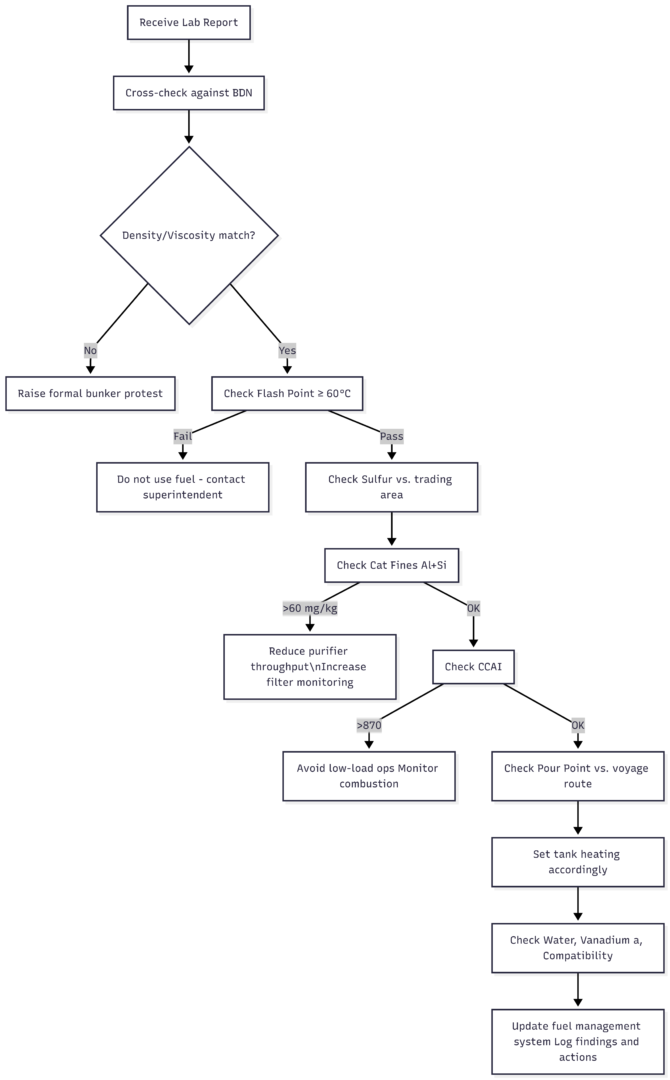
The Report Reading Process: A Workflow
ISO 8217 Quick Reference — Key Limits for RMG 380
| Property | Test Method | Limit |
|---|---|---|
| Density at 15°C | ISO 3675 / 12185 | Max 991.0 kg/m³ |
| Kinematic Viscosity at 50°C | ISO 3104 | Max 380 mm²/s |
| Flash Point | ISO 2719 | Min 60°C |
| Water Content | ISO 3733 | Max 0.50% v/v |
| Sulfur Content | ISO 8754 | Max 3.50% m/m (0.50% global cap, 0.10% ECA) |
| Aluminum + Silicon | IP 501/470 | Max 60 mg/kg |
| Vanadium | IP 501/470 | Max 350 mg/kg |
| Ash | ISO 6245 | Max 0.10% m/m |
| Total Sediment (aged) | ISO 10307-2 | Max 0.10% m/m |
| Pour Point (upper) | ISO 3016 | Max 30°C (summer) / 0°C (winter) |
| CCAI | Calculated | Max 870 (guideline) |
Conclusion
A fuel oil lab analysis report is not a formality. It is a precision instrument that, read correctly, protects your engines, keeps your vessel in regulatory compliance, and gives you the information to make intelligent decisions about fuel handling from the moment the bunker hose disconnects.
The ten parameters covered here — density, viscosity, water content, flash point, sulfur, cat fines, CCAI, pour point, vanadium/sodium, and compatibility — each tell a distinct story about the fuel you have taken on. Cross-reference the report with your BDN, act on the findings before transferring fuel to the service tank, and keep a record of corrective actions taken. That discipline, applied consistently, is what separates a well-run engine room from one that is perpetually fighting fires.
Always keep your auto backwash filters operational and never bypass them. The cost of a choked filter is trivial compared to the cost of cat-fine damage to a set of fuel pumps or cylinder liners.
Always verify fuel parameters against ISO 8217 and applicable flag state/classification society requirements. Consult your technical superintendent before taking action on out-of-spec results.
Happy Boating!
Share Interpreting an Oil Analysis Report – The Top 10 Tips with your friends and leave a comment below with your thoughts.
Read Why Ballast Water must be Treated until we meet in the next article.