Critical Speed of Marine Diesel Engines: Resonance Risks and Mitigation
Explore critical speed in marine diesel engines, resonance risks, and mitigation strategies for safe operation. Learn causes and solutions.
Marine diesel engines power the vast majority of the world’s ships, from cargo vessels to icebreakers. These engines operate under extreme conditions, driving massive propellers through turbulent waters. However, one phenomenon—critical speed—poses a significant risk to their reliability and longevity. Critical speed occurs when an engine’s rotational frequency aligns with the natural frequency of the engine or surrounding structure, such as the ship’s hull, leading to resonance. This resonance amplifies vibrations, potentially causing excessive stress, noise, and even catastrophic failure. Understanding critical speed, its causes, and mitigation strategies is essential for marine engineers, ship designers, and operators to ensure safe and efficient vessel operation.
This article delves into the mechanics of critical speed in marine diesel engines, explores the resonance risks, and outlines practical mitigation techniques. Drawing from real-world case studies and technical insights, it provides a comprehensive guide for addressing this critical issue.
What is Critical Speed in Marine Diesel Engines?
Critical speed refers to the rotational speed (measured in revolutions per minute, or RPM) at which an engine’s operating frequency matches the natural frequency of the engine, its components, or the surrounding structure, such as the ship’s hull or bulkheads. This alignment triggers resonance, a condition where vibrations are amplified, leading to increased stress on mechanical components.
Types of Vibrations
Critical speed can manifest in two primary forms of vibration:
- Torsional Vibration: This involves twisting oscillations along the rotational axis of the crankshaft, propeller shaft, or drivetrain. Torsional vibrations arise from cyclic torque variations in reciprocating engines, where torque peaks during the expansion stroke and dips during compression.
- Lateral Vibration: Also known as radial vibration, this occurs perpendicular to the rotational axis, affecting components like shafts, bearings, or the hull. Lateral vibrations are often excited by unbalanced forces or structural resonance.
Both types can lead to excessive noise, crew discomfort, and mechanical damage if not addressed. For example, prolonged operation at critical speed can cause fatigue in crankshafts, bearings, or couplings, leading to premature failure.
Resonance and Its Dangers
Resonance occurs when the frequency of an external force (e.g., engine rotation or propeller blade passage) matches the natural frequency of a system. In marine applications, this could involve the engine, shafting, or hull. The resulting amplified vibrations can:
- Increase stress on components, leading to cracks or fractures.
- Generate excessive noise, affecting crew comfort and communication.
- Cause misalignment or wear in bearings and couplings.
- In extreme cases, lead to catastrophic failure of critical components like the crankshaft or propeller shaft.
To illustrate, consider a case study of a 98-meter Arctic icebreaker built in the early 1980s. A plaque in the engine room noted a critical speed range of 90–110 RPM, coinciding with excessive vibrations at the rear bulkhead. Tests revealed a natural frequency of 7280 cycles per minute (cpm, or 121 Hz), excited longitudinally when both engines operated at 100 RPM. Shutting off one engine eliminated the vibrations, highlighting the complex interplay of engine operation and structural resonance.
Causes of Critical Speed in Marine Diesel Engines
Several factors contribute to critical speed in marine diesel engines. Understanding these is key to designing and operating vessels that avoid resonance-related issues.
1. Engine and Shaft Dynamics
The primary source of critical speed is the engine’s cyclic operation. In reciprocating engines, each cylinder delivers torque unevenly, with peaks during the expansion stroke and troughs during compression. This creates periodic excitations that can induce torsional vibrations. The frequency of peak torque is calculated as:
Frequency (Hz) = (Number of cylinders × RPM) / 60For example, a 6-cylinder engine running at 100 RPM produces a torque frequency of:
(6 × 100) / 60 = 10 HzIf this frequency or its harmonics (e.g., 20 Hz, 30 Hz) aligns with the natural frequency of the crankshaft or shafting, resonance occurs.
Shaft dynamics also play a role. The critical speed of a shaft depends on:
- Length: Longer shafts have lower natural frequencies, making them more susceptible to resonance at lower RPMs.
- Diameter: Thinner shafts are less stiff, reducing their critical speed.
- Material: The shaft’s material affects its elasticity and natural frequency.
- Support Stiffness: Bearings and supports influence the shaft’s vibrational behavior.
2. Propeller-Induced Vibrations
Propellers can excite vibrations as their blades pass close to the hull, creating pressure pulses. The vane pass frequency is calculated as:
Vane Pass Frequency (Hz) = (Number of blades × Shaft RPM) / 60For a 4-blade propeller at 100 RPM:
(4 × 100) / 60 = 6.67 HzIf this frequency or its harmonics matches the hull’s natural frequency, resonance can occur. In the icebreaker case, the vane pass frequency (400 RPM or 6.67 Hz) was far from the observed 121 Hz, ruling it out as the primary cause.
3. Structural Resonance
The ship’s hull, bulkheads, or other structures can resonate if their natural frequencies align with engine or propeller excitations. For instance, the icebreaker’s rear bulkhead had a natural frequency of 7280 cpm (121 Hz), excited at 90–110 RPM. This suggests the hull itself amplified vibrations, possibly due to its design or material properties.
4. Other Sources
Additional sources of vibration include:
- Exhaust Blasts: High-energy exhaust pulses can excite structural frequencies, especially if two engines operate synchronously. However, in the icebreaker case, varying diesel engine combinations did not affect the 121 Hz vibration, ruling out exhaust as the cause.
- Cavitation: Propeller cavitation can generate high-frequency vibrations, but this is less likely at low RPMs like 90–110.
- Rudders or Appendages: Vibrating rudders or other appendages can contribute, though their impact is typically localized.
- Turbulent Flow: Wake or turbulent water flow near the hull could excite structural resonance, though this is harder to quantify.
Critical Speed in Older vs. Modern Vessels
The icebreaker case raises a key question: Do all boats have critical speed zones, or is this issue confined to older vessels built before modern design tools like Finite Element Method (FEM) became widespread?
Older Vessels (Pre-1980s)
Vessels built in the early 1980s, like the icebreaker, often relied on empirical design and physical trials to identify critical speeds. Manufacturers conducted sea trials to measure vibrations and marked critical speed ranges (e.g., 90–110 RPM) on plaques or maneuvering panels. These ranges were to be avoided during continuous operation, as prolonged exposure could damage components.
The limitations of pre-FEM design meant that critical speeds were sometimes discovered only after construction, leading to operational restrictions. For example, the icebreaker’s plaque indicated a known issue, likely identified during trials, but the underlying cause (e.g., bulkhead resonance) was not fully resolved.
Modern Vessels
Modern ship design leverages advanced tools like FEM, computational fluid dynamics (CFD), and vibration analysis to predict and mitigate critical speeds during the design phase. These tools allow engineers to:
- Model the natural frequencies of the engine, shafting, and hull.
- Optimize shaft dimensions, bearing placement, and material properties.
- Simulate propeller-hull interactions to minimize pressure pulses.
- Design dampers or flexible couplings to absorb vibrations.
As a result, modern vessels are less likely to have pronounced critical speed zones that require operational restrictions. However, critical speeds still exist, as no system is entirely immune to resonance. Modern engines often incorporate:
- Electronic Controls: These limit dwell time in critical speed ranges, using quick-pass functions to accelerate or decelerate through barred zones.
- Torsional Dampers: Viscous or tuned-mass dampers absorb vibrational energy.
- Flexible Couplings: These decouple vibrations between the engine and shafting.
Despite these advancements, complex vessels like icebreakers, which operate in extreme conditions, may still encounter critical speed issues due to their unique structural and operational demands.
Risks of Operating at Critical Speed
Operating a marine diesel engine at critical speed poses several risks:
- Mechanical Damage: Resonance-induced stress can cause fatigue failure in crankshafts, bearings, or couplings. For example, torsional vibrations can lead to crankshaft fractures, a costly and dangerous failure.
- Structural Damage: Hull or bulkhead resonance can weaken welds, loosen fasteners, or crack panels.
- Crew Discomfort: Excessive vibrations increase noise and vibration exposure, affecting crew performance and safety.
- Reduced Efficiency: Vibrations can cause misalignment, increasing fuel consumption and wear.
- Safety Hazards: In extreme cases, resonance can compromise vessel stability or control, especially in rough seas.
To mitigate these risks, operators must avoid prolonged operation at critical speeds and implement design or maintenance strategies to minimize resonance.
Mitigation Strategies for Critical Speed
Effective mitigation of critical speed involves a combination of design, operational, and maintenance strategies. Below are the key approaches, supported by practical examples and technical insights.
1. Design Optimization
- Shaft Design: Increase shaft diameter or add intermediate bearings (e.g., plumber blocks) to raise the critical speed above the operating range. For instance, a 20-inch shaft in the icebreaker could be supported by additional bearings to reduce free length and increase stiffness.
- Material Selection: Use high-stiffness materials like alloy steel for shafts to shift natural frequencies.
- Hull Stiffening: Reinforce bulkheads or add damping materials to alter the hull’s natural frequency. In the icebreaker case, stiffening the rear bulkhead could shift its 121 Hz natural frequency.
- Propeller Design: Optimize blade count and shape to minimize pressure pulses. CFD can predict vane pass frequencies and their impact on the hull.
2. Vibration Damping
- Torsional Dampers: Install viscous or tuned-mass dampers on the crankshaft to absorb torsional vibrations. These are common in modern engines and can reduce peak stresses by 30–50%.
- Flexible Couplings: Use elastic couplings between the engine and shaft to decouple vibrations. These are effective for both torsional and lateral vibrations.
- Lanchester Balancers: These rotating counterweights, driven by the engine, cancel out vibrations. They are often integrated into the camshaft drive chain.
- Oil Film Damping: Ensure proper bearing lubrication to maximize damping through oil films.
3. Operational Controls
- Quick-Pass Function: Modern engine control systems automatically accelerate or decelerate through critical speed ranges. For example, during acceleration, the system keeps RPM below the lower limit (e.g., 90 RPM), and during deceleration, it stays above the upper limit (e.g., 110 RPM).
- Critical Speed Indicators: Mark critical speed ranges in red on maneuvering panels and install warning lamps in the bridge and engine control room (ECR). This was evident in the icebreaker, where the 90–110 RPM range was clearly labeled.
- Operator Training: Train crew to avoid prolonged operation at critical speeds and recognize vibration symptoms.
4. Maintenance Practices
- Regular Vibration Monitoring: Use sensors to detect changes in vibration patterns, indicating potential resonance issues. Portable vibration analyzers can measure frequencies like the 121 Hz observed in the icebreaker.
- Shaft Alignment: Ensure proper alignment of shafts, bearings, and couplings to minimize unbalanced forces.
- Propeller Inspection: Check for damage or cavitation, which can alter vibrational characteristics.
- Bearing Maintenance: Replace worn bearings to maintain stiffness and damping properties.
5. Retrofitting Solutions
For older vessels like the icebreaker, retrofitting can address critical speed issues:
- Add Counterweights: Bolt counterweights to crankwebs to balance the engine, similar to balancing car wheels.
- Install Vibration Absorbers: Fit crankshaft vibration absorbers to dissipate energy.
- Sectionalize Shafting: Divide long shafts into shorter sections with couplings to alter natural frequencies.
Case Study: Arctic Icebreaker Vibration Analysis
To contextualize these strategies, let’s revisit the Arctic icebreaker case. The vessel, a 98-meter Class III icebreaker, experienced excessive vibrations at 90–110 RPM, as indicated on a plaque. Key observations:
- Vibration Characteristics: The rear bulkhead vibrated longitudinally at 7280 cpm (121 Hz) when both electric motors (driving 20-inch shafts with 4-blade propellers) operated at 100 RPM. Shutting off one motor eliminated the vibrations.
- Exclusions: Tests ruled out diesel engines, exhaust blasts, and vane pass frequency (6.67 Hz) as causes. Shaft vibrations were low, suggesting the hull was the primary resonator.
- Hypothesized Cause: The combined operation of both motors likely excited a harmonic or structural mode in the rear bulkhead, possibly amplified by turbulent flow or propeller pressure pulses.
Proposed Solutions
- Structural Reinforcement: Stiffen the rear bulkhead with additional plating or braces to shift its natural frequency above 121 Hz.
- Damping Materials: Apply viscoelastic damping layers to the bulkhead to absorb vibrational energy.
- Operational Adjustment: Program the control system to avoid 90–110 RPM during continuous operation, using a quick-pass function.
- Vibration Monitoring: Install sensors to track bulkhead vibrations and alert operators to resonance conditions.
These solutions balance cost, feasibility, and effectiveness for an older vessel, demonstrating how mitigation strategies can be tailored to specific cases.
Chart: Critical Speed Mitigation Workflow
Below is a flowchart illustrating the process for identifying and mitigating critical speed issues in marine diesel engines, created using syntax.
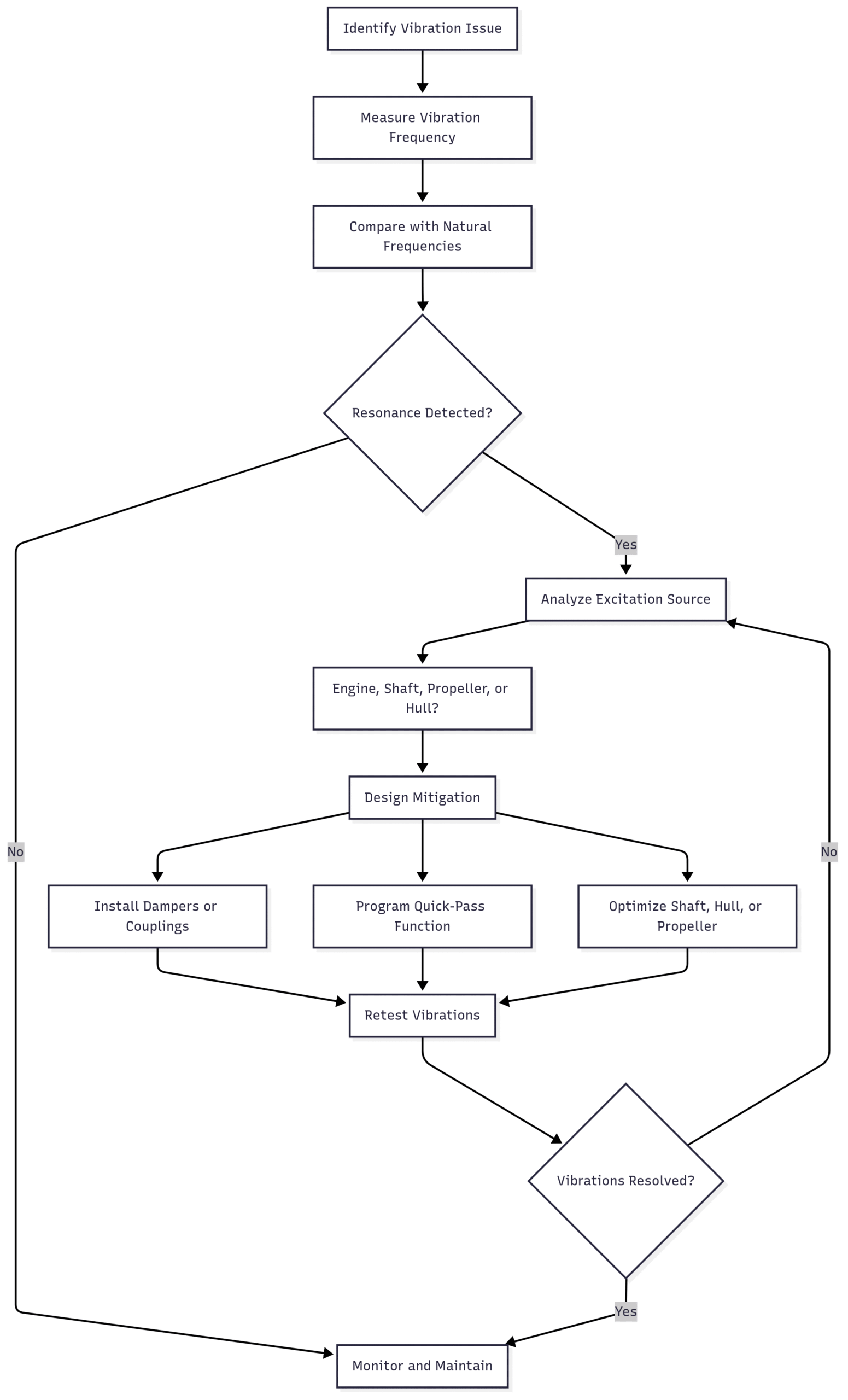
This workflow guides engineers through diagnosis, analysis, and mitigation, ensuring a systematic approach to resolving critical speed issues.
Specifications and Costs of Mitigation Solutions
The following table outlines common mitigation solutions, their specifications, and estimated costs (in USD, based on typical marine engineering practices). Note that costs vary by vessel size, location, and labor rates.
| Solution | Specifications | Estimated Cost |
|---|---|---|
| Torsional Damper | Viscous damper, 500–1000 Nm capacity, fits crankshaft | $5,000–$15,000 |
| Flexible Coupling | Elastic coupling, 20–50 kNm torque capacity, aligns with 20-inch shaft | $10,000–$25,000 |
| Lanchester Balancer | Counterweight shaft, driven by camshaft chain, balances 6-cylinder engine | $15,000–$30,000 |
| Shaft Bearing (Plumber Block) | Supports 20-inch shaft, increases stiffness, marine-grade steel | $2,000–$5,000 per unit |
| Hull Reinforcement | 10 mm steel plating, 5 m² area, welded to bulkhead | $20,000–$50,000 |
| Vibration Monitoring System | 4-channel sensor system, real-time frequency analysis | $10,000–$20,000 |
| Quick-Pass Control Software | ECU programming for RPM avoidance, compatible with modern control systems | $5,000–$10,000 |
These costs are indicative and should be verified with marine engineering suppliers. Retrofitting older vessels like the icebreaker may incur higher labor costs due to accessibility challenges.
Conclusion
Critical speed in marine diesel engines is a complex but manageable challenge. By understanding the interplay of engine dynamics, shafting, propellers, and hull resonance, engineers can design and operate vessels to minimize risks. Modern tools like FEM and CFD have reduced the prevalence of critical speed issues, but older vessels and complex designs still require careful management. Through optimized design, damping solutions, operational controls, and regular maintenance, critical speed risks can be mitigated, ensuring safe, efficient, and reliable marine operations.
For vessels like the Arctic icebreaker, a combination of structural reinforcement, damping, and operational adjustments offers a practical path forward. By applying these principles, marine engineers can navigate the challenges of critical speed, keeping ships sailing smoothly across the world’s oceans.
References
- Heywood, J. B. (2018). Internal Combustion Engine Fundamentals (2nd ed.). McGraw-Hill.
- Taylor, C. F. (1985). The Internal Combustion Engine in Theory and Practice (Vol. 1 & 2). MIT Press.
- International Organization for Standardization. (2010). ISO 3046-5: Reciprocating internal combustion engines – Performance – Part 5: Torsional vibrations.
- Wilson, W. K. (1956). Practical Solution of Torsional Vibration Problems. Chapman & Hall.
- Wharton, A. J. (1991). Diesel Engines (3rd ed.). Step-By-Step.
Happy Boating!
Share Critical Speed of Marine Diesel Engines: Resonance Risks and Mitigation with your friends and leave a comment below with your thoughts.
Read Turbocharger Surging: What It Is and Why It Matters until we meet in the next article.