8 Common Problems of Ship’s Incinerator Mariners Should Know
A ship’s incinerator is one of the most important auxiliary machines on board. It burns solid and liquid waste generated during normal ship operations — sludge oil, oily rags, food waste, and combustible materials — reducing disposal costs and keeping the vessel compliant with MARPOL Annex VI environmental regulations. Without a functioning incinerator, waste management at sea becomes a serious operational and legal problem.
Like any shipboard machinery, incinerators are prone to wear, fouling, and operational faults. Understanding the most common problems, their root causes, and the correct remedies is essential for every marine engineer and officer. Neglecting these issues doesn’t just reduce efficiency — it can lead to safety incidents, Port State Control (PSC) deficiencies, fines, and vessel detention.
This guide covers all 8 common ship incinerator problems in detail, with causes, solutions, and a maintenance framework to keep the system running reliably.
How a Ship Incinerator Operates
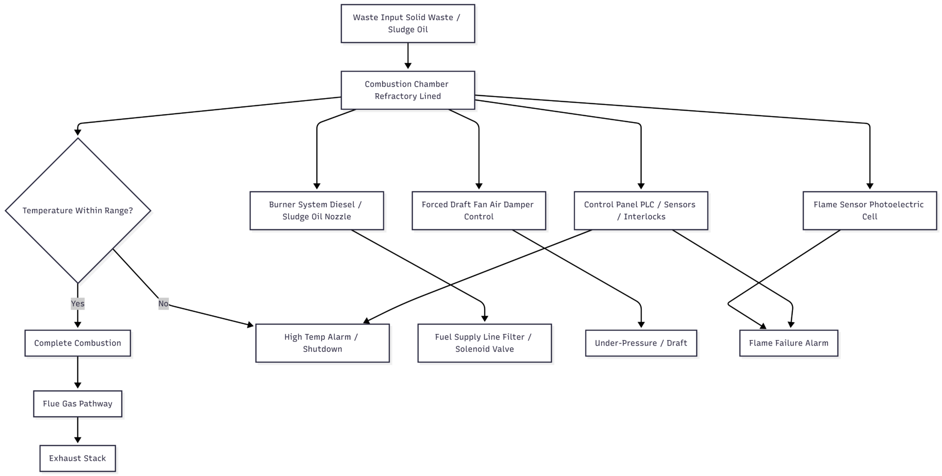
Before troubleshooting problems, it’s worth understanding the basic system. A shipboard incinerator burns waste inside a refractory-lined combustion chamber. A diesel oil or sludge oil burner generates the heat. A forced draft fan supplies combustion air through a controlled air damper. A flue gas system exhausts combustion gases. A control panel with sensors, alarms, and safety interlocks monitors and regulates the entire process automatically.
When any component in this chain fails, the result is an alarm, a trip, or degraded performance — all of which require prompt diagnosis and action.
BLEVE System Flow: Ship Incinerator Process
8 Common Ship Incinerator Problems
1. Flame Failure Alarm
Flame failure is the single most frequent alarm mariners encounter during incinerator operation. The flame sensor — a photoelectric cell — continuously monitors combustion. When it detects no flame, or receives a corrupt signal due to contamination, it triggers an alarm and shuts down the burner as a safety measure.
Common Causes:
- Dirty or fouled photoelectric flame sensor
- Blocked diesel oil nozzle
- Faulty or misaligned ignition spark electrodes
- Defective solenoid valve or coil
- Incorrect air damper position (too open or too restricted)
- Clogged fuel line filter
- Dirty burner flame shroud or blast tube
Solutions:
- Remove, clean, and reinstall the flame sensor. Replace if defective.
- Replace blocked diesel oil nozzles with clean spares.
- Clean and readjust spark electrode gap. Carbon buildup on electrodes is a common, overlooked cause of repeated ignition failure.
- Test the solenoid valve for correct operation. Replace the valve or coil if defective.
- Verify air damper opening position and correct as needed.
- Clean the burner blast tube, flame shroud, and fuel line filter as part of every pre-operation check.
A critical point often missed on board: spark electrode gap misalignment or excessive carbon deposit causes repeated ignition failure even when the fuel system is clean. Always inspect electrodes when flame failure persists after sensor cleaning.
2. High Combustion Chamber Temperature Alarm
When the combustion chamber temperature exceeds its set limit, the alarm activates and the unit may trip. This is not simply a sign of good combustion — it signals that heat generation has gone beyond safe design limits.
Common Causes:
- Excessive quantity of solid waste loaded in a single batch
- Excessively high sludge oil feed rate
- Faulty temperature sensor giving a false high reading
- Blocked slag outlet or clogged floor slot in the combustion chamber
- Deteriorated refractory condition concentrating heat in localised zones
Solutions:
- Before assuming a real temperature event, verify sensor functionality by checking calibration or comparing with an alternate reading.
- Reduce waste batch size and sludge feed rate to within recommended limits.
- Clear any blockage at the slag outlet or chamber floor slot.
- Inspect refractory lining and repair damaged sections immediately.
3. High Flue Gas Temperature Alarm
Flue gas temperature is monitored downstream of the combustion chamber to confirm gases are cooling properly before being exhausted. Elevated readings at this point point to a problem in the exhaust or cooling pathway — not in the combustion zone itself.
Common Causes:
- Faulty or miscalibrated flue gas temperature sensor
- Fouled heat exchanger or clogged cooling panel slot
- Blocked air cooling inlet
- Leaking or defective solenoid valve
- Leaking dosing pump stator
- Throttling brick dislodged from its position
Solutions:
- Calibrate or replace the temperature sensor.
- Clean the heat exchanger surfaces and cooling panel slots.
- Inspect and clear the air cooling inlet.
- Test solenoid valve operation. Replace if found to be leaking.
- Re-seat or replace the throttling brick.
- Check dosing pump stator for leakage and replace the stator if worn.
4. Sludge Oil Leaking
Sludge oil leaks from the combustion chamber represent a direct fire hazard. Leaks typically appear at the base plate corners of the combustion chamber and must be treated as urgent.
Common Causes:
- Improper opening of the oil burner air damper
- Excessively low under-pressure (negative pressure) inside the chamber
- Atomizing valve closed or not sufficiently open
- Incorrect valve states set in the PLC (Programmable Logic Controller)
- Blocked sludge nozzle atomizing slot
Solutions:
- Ensure the atomizing slot is open between ¾ and 1 full turn — not fully closed, not over-opened.
- Verify all PLC valve positions match the settings specified in the manufacturer’s manual.
- Check the under-pressure control function and correct if chamber pressure is too low.
- Inspect air damper operation and correct its opening position.
- Clean the sludge nozzle atomizing slot if blocked.
- Inspect the base plate for cracks. A cracked base plate must be repaired before the unit is returned to service.
5. Cracks in Refractory Lining of the Combustion Chamber
The refractory lining is the ceramic insulation bonded to the inside of the combustion chamber shell. It protects the steel structure from extreme heat. Cracks or failures in the lining are a serious structural issue — if left unrepaired, the shell will overheat, warp, and potentially develop external burn-through.
Common Causes:
- Thermal shock from adding cold water to the sludge tank while sludge is actively burning at high temperature
- Machinery vibration transmitted through the deck to the incinerator body
- Leaking door gaskets allowing cold air to enter the hot chamber suddenly
- Failure to follow the manufacturer’s gradual heat-up and cool-down procedures during startup and shutdown
Solutions:
- Never fill the sludge tank with water while burning is in progress — this is the most common single cause of refractory cracking.
- Reinforce deck support structures around the incinerator to reduce transmitted vibration.
- Inspect door gaskets regularly and replace at the first sign of wear or leakage.
- Always follow a controlled startup and shutdown temperature ramp as per the manufacturer’s manual.
- Repair small cracks promptly using compatible refractory cement. Extensive or deep cracking requires full refractory relining during a scheduled maintenance period.
6. Draft Failure / Low Under-Pressure Alarm
Adequate draft — the negative pressure maintained inside the combustion chamber — is essential for drawing combustion air through and expelling flue gases correctly. A draft failure alarm indicates airflow has been significantly disrupted, leading to incomplete combustion and potential smoke generation.
Common Causes:
- Faulty or failed draft pressure sensor
- Damaged or compressed door gasket allowing air ingress and pressure equalisation
- Broken or slipping fan belt
- Incorrect fan rotation direction after maintenance
- Flue gas damper failing to open fully
- Leakage in the sensor impulse tube
Solutions:
- Test the pressure sensor and replace if faulty — this is the most common cause of false alarms.
- Inspect the door gasket for compression and sealing integrity. Replace if damaged.
- Check fan belt tension and condition. Replace if broken or excessively worn.
- After any maintenance involving the fan motor, confirm rotation direction matches the specification arrow.
- Test the flue gas damper for full and free operation. Repair if stuck or slow to open.
- Inspect and seal any leaks in the sensor tube line.
7. Leaking Mechanical Seal on the Sludge Pump
The sludge oil pump delivers fuel to the sludge burner. A leaking mechanical seal allows sludge to escape at the pump body, creating a fire risk and reducing burner fuel pressure.
Common Causes:
- Sludge pump running dry for an extended period (no sludge in the suction line)
- Large debris or hard solids in the sludge damaging the lapped seal faces
- Normal wear over time
Solutions:
- Never run the sludge pump dry. Always confirm adequate sludge level in the service tank before starting the pump.
- If debris contamination is suspected, shut down the pump, flush and clean suction lines thoroughly, then restart.
- Replace the mechanical seal at the earliest maintenance opportunity once a leak is confirmed. Running on a worn seal accelerates damage to the shaft sleeve.
8. Leakage at Diesel Oil Pump Shaft End
A leak at the diesel oil pump shaft seal reduces burner fuel pressure and creates a fire risk in the incinerator room.
Common Causes:
- Blocked or restricted return line creating excessive backpressure on the shaft seal
- Normal wear of the shaft seal over time
Solutions:
- Open the return valve fully or remove any obstruction in the return line.
- Replace the shaft end seal. This is a straightforward maintenance task that should not be deferred once a leak is identified.
Problem Summary Table
| # | Problem | Primary Cause | Key Solution |
|---|---|---|---|
| 1 | Flame Failure Alarm | Dirty sensor, blocked nozzle, faulty electrode | Clean sensor, replace nozzle, adjust electrode |
| 2 | High Combustion Chamber Temp | Excess waste load, faulty sensor, blocked slag outlet | Reduce loading, verify sensor, clear outlet |
| 3 | High Flue Gas Temperature | Fouled heat exchanger, sensor fault, blocked cooling | Clean system, calibrate/replace sensor |
| 4 | Sludge Oil Leaking | Low under-pressure, blocked nozzle, PLC error | Adjust atomizing valve, check PLC, inspect base plate |
| 5 | Refractory Cracks | Thermal shock, vibration, leaking door gasket | Gradual temp cycling, reinforce deck, replace gasket |
| 6 | Draft Failure / Low Pressure | Faulty sensor, broken fan belt, blocked damper | Replace belt, test sensor, inspect damper |
| 7 | Sludge Pump Seal Leak | Dry running, debris in sludge | Prime pump properly, flush lines, replace seal |
| 8 | DO Pump Shaft Leak | Blocked return line, worn seal | Clear return, replace shaft seal |
Minimum Operating Temperature Requirements (MARPOL / IMO)
Maintaining correct combustion temperature is a regulatory requirement, not just a performance target. Operating below minimum temperatures causes incomplete combustion, black smoke, and MARPOL violations.
| Waste Type | Minimum Combustion Temperature |
|---|---|
| General solid waste | 850°C |
| Sludge oil / liquid waste | 850°C (primary combustion zone) |
| Flue gas (secondary chamber) | 1,200°C (where secondary chamber fitted) |
| Plastics | 850°C minimum (higher recommended) |
| Prohibited materials (PCBs, heavy metals) | Not permitted for incineration |
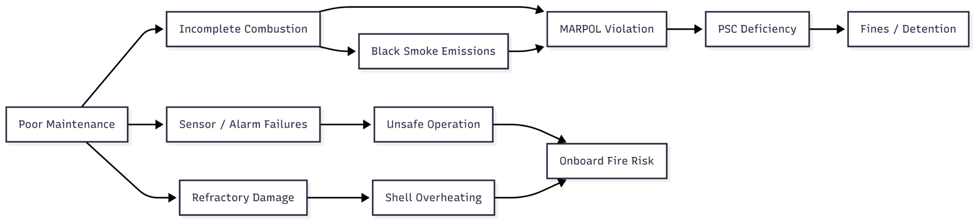
Consequences of Poor Incinerator Maintenance
Neglecting incinerator maintenance creates compounding risks across safety, environment, and commercial operations.
Preventive Maintenance Checklist
A structured maintenance routine eliminates the majority of incinerator problems before they develop into operational failures.
Before Every Operation:
- Confirm flame sensor is clean and seated correctly
- Verify sludge level in the service tank before starting the sludge pump
- Check air damper position and operation
- Confirm all PLC valve states match the manual
Weekly:
- Inspect burner nozzles for blockage or wear
- Test solenoid valve operation
- Check door gasket condition and seal integrity
- Inspect fan belt tension
Monthly:
- Clean heat exchanger surfaces and cooling panel slots
- Inspect refractory lining for cracks or spalling
- Test all safety interlocks: door interlock, high-temperature trip, flame failure detector
- Calibrate temperature and pressure sensors
- Check under-pressure control function
At Each Port Call or Dry Dock:
- Full inspection of refractory lining. Repair or reline as required.
- Inspect and replace mechanical seals on sludge pump and DO pump if showing wear
- Inspect flue gas damper mechanism for free operation
- Review and update the maintenance log
Key Takeaway
A ship’s incinerator requires consistent, attentive maintenance to operate safely and remain within MARPOL compliance. The eight problems covered in this article — from flame failure alarms and temperature faults to refractory cracking and pump seal leaks — account for the vast majority of incinerator downtime on board. Most can be prevented entirely through routine inspection and by following the manufacturer’s operational procedures correctly. Early detection, correct diagnosis, and prompt repair protect the vessel from environmental violations, PSC deficiencies, and the more serious risk of an onboard fire caused by an uncontrolled sludge leak or combustion chamber failure.
Happy Boating!
Share 8 Common Problems of Ship’s Incinerator Mariners Should Know with your friends and leave a comment below with your thoughts.
Read What is Boiling Liquid Expanding Vapour Explosion (BLEVE) on Gas Carrier Ships? until we meet in the next article.