Boiler Mountings: A Comprehensive List
The marine boiler is one of the oldest and most indispensable pieces of machinery in a ship’s engine room. In the early era of steam shipping, it powered the entire vessel. Today, boilers are still central to heating, power generation, cargo management, and crew welfare — and their safe operation depends entirely on a set of dedicated fittings known as boiler mountings.
Installing a boiler is only the first step. A boiler cannot be considered operationally complete — or legally compliant — until all required mountings are fitted, tested, and certified. These components are not optional extras; they are the control and safety infrastructure of the entire steam system.
What Are Boiler Mountings?
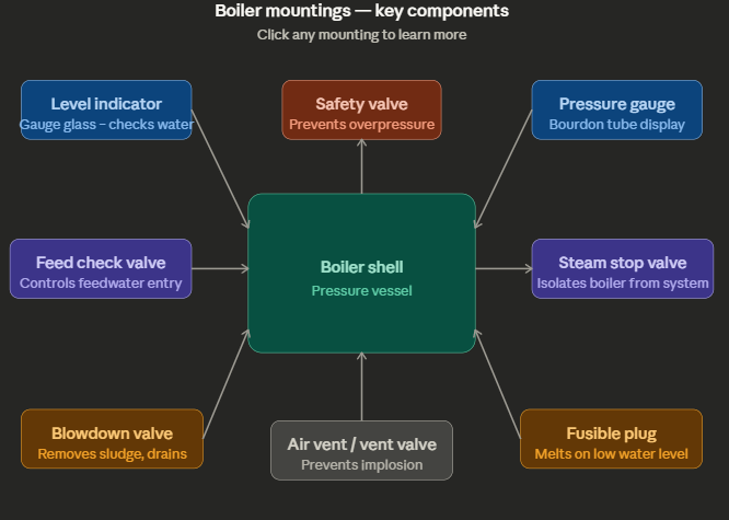
Boiler mountings are fittings attached directly to the boiler shell or drum that enable safe, controlled operation. They regulate steam flow, monitor water levels, manage pressure, allow maintenance access, and protect against catastrophic failure.
They are distinct from boiler accessories (such as economizers, superheaters, and air preheaters), which improve efficiency but are not directly safety-critical in the same way. Mountings are mandatory — accessories are complementary.
| Feature | Mountings | Accessories |
|---|---|---|
| Purpose | Safe operation and pressure control | Efficiency and performance improvement |
| Location | Directly on the boiler shell | Associated pipework and systems |
| Mandatory? | Yes, per classification society rules | No, though strongly recommended |
| Examples | Safety valve, gauge glass, stop valve | Economizer, superheater, feed water heater |
Complete List of Boiler Mountings
1. Main Steam Stop Valve
The main steam stop valve is mounted directly on the steam space of the boiler shell or superheater outlet header. Its job is to control or completely isolate the flow of steam from the boiler into the ship’s steam distribution system.
On vessels where multiple boilers share a common steam line, this valve ensures that in the event of a burst tube or pressure drop in one boiler, steam from adjacent boilers cannot backfeed into the damaged unit. It is typically a screw-down, non-return type valve, with the body cast in iron and the seat in gunmetal. Some versions include automatic closing devices for emergency isolation.
2. Auxiliary Steam Stop Valve
A smaller variant of the main stop valve, this fitting is positioned on the auxiliary steam line — a secondary steam supply branching off for lower-demand services such as heating, domestic use, and smaller deck equipment. Like its counterpart, it is a non-return type valve to prevent backflow under system failure conditions. In some configurations, a de-superheater may be installed alongside it to reduce steam temperature to the required service level.
3. Boiler Safety Valve
This is the single most critical boiler mounting. The safety valve is designed to open automatically and release excess steam whenever internal pressure exceeds a pre-set safe limit, protecting the boiler from explosion.
Safety valves are always installed in pairs — one set to lift at a slightly lower pressure than the other — to provide redundancy. If one valve fails, the second ensures the boiler does not over-pressurize. The lifting pressure is set and locked in the presence of a classification society surveyor before installation, and cannot be altered without authorization.
Two common types are used on ships: spring-loaded safety valves (the most common) and lever-type safety valves. The superheater safety valve is configured to open first, maintaining steam flow through the superheater tubes even during blow-off, preventing thermal damage from dry overheating.
4. Water Level Indicator (Gauge Glass)
Gauge glasses are fitted in pairs directly to the boiler drum to provide a direct, visual indication of the water level inside. The level of water in the boiler is one of the most operationally critical parameters — too low and the heating surfaces overheat; too high and water carryover into the steam system can cause water hammer and turbine damage.
Construction of the gauge glass is determined by boiler operating pressure. High-pressure boilers use reflex or bi-color gauges, while lower-pressure units may use simpler transparent glass arrangements. In addition to the local gauges, remote reading transmitters may be installed in the engine control room for continuous monitoring.
5. Feed Check Valve
The feed check valve regulates the entry of feedwater from the feed pump into the boiler. It is a non-return valve, meaning it allows flow in one direction only — into the boiler — and automatically prevents boiler water from flowing back into the feed line if pump pressure drops.
Both main and auxiliary feed check valves are fitted, with clear visual indication of open or closed status for safe operation. The main valve is positioned on the feed line at a convenient point for local operation.
6. Pressure Gauge
A Bourdon tube pressure gauge is fitted to the boiler drum and, where applicable, to the superheater outlet and other key pressure points in the steam system. It provides a real-time local readout of steam pressure, enabling the engineer on watch to verify that the boiler is operating within safe and efficient parameters.
Pressure switches connected to the gauge circuit can trigger alarms or initiate automatic burner shutdown if pressure drifts outside acceptable limits.
7. Blow-off Valve (Bottom Blowdown Valve)
Positioned at the lowest point of the boiler water drum or shell, the bottom blowdown valve has two primary uses: removing accumulated sludge and sediment from the base of the boiler, and partially or fully draining the boiler for maintenance or water treatment purposes.
Partial blowdown is routinely used when the total dissolved solids (TDS) in the boiler water rise above acceptable limits — discharging a controlled volume and replacing it with fresh feedwater dilutes the concentration. A full blowdown completely empties the boiler, typically during scheduled dry-dock periods.
8. Scum Blowdown Valve
Unlike the bottom blowdown valve, the scum valve is fitted at the normal water level using a shallow dish-type arrangement. Its purpose is to remove floating surface impurities — oil contamination, foaming agents, and similar residues — that accumulate at the water surface and can lead to priming (water carryover into the steam).
This valve is used during boiler operation, particularly after any fuel oil contamination of the feed system is suspected.
9. Air Release Valve (Vent Valve)
The air vent is fitted to the highest point of the boiler drum and headers. During initial startup from cold, air trapped inside the boiler must be purged before pressure builds — otherwise, air pockets reduce heat transfer efficiency and can cause local hot spots.
During shutdown and depressurization, the same valve prevents a dangerous vacuum from forming inside the boiler shell as steam condenses. A vacuum strong enough to cause the shell to buckle inward — an implosion — can be just as catastrophic as an overpressure event.
10. Fusible Plug
The fusible plug is a passive safety device fitted in the furnace crown or firebox of certain boiler types. It contains a core of low-melting-point metal (typically a tin-bismuth alloy) calibrated to melt at a temperature below that which would cause structural damage to the boiler shell.
If the water level drops dangerously low and the heating surfaces become uncovered, the fusible plug melts through, releasing steam into the furnace and extinguishing the fire. It provides a final fail-safe when all other water level controls and alarms have failed.
11. Low Water Level Alarm
This device continuously monitors the water level in the boiler drum and triggers an audible and visual alarm when the level drops to a pre-set low threshold. A second, lower trip point — the Low-Low level alarm — initiates an automatic burner cutoff to prevent the boiler from operating dry, which would rapidly overheat and damage the pressure vessel.
Some systems also include a High Water level alarm to prevent excessive water from being carried over into the steam pipework.
12. Automatic Feed Water Regulator
The feedwater regulator automatically maintains the correct water level in the boiler drum under all load conditions, adjusting the feedwater flow rate in response to changes in steam demand. This is particularly critical on water-tube boilers with high evaporation rates, where manual control would be inadequate to prevent dangerous water level fluctuations.
Modern systems use multi-element control — sensing steam flow, feedwater flow, and drum level simultaneously — for precise regulation.
13. TDS Sensor and Probe
On modern marine boilers, a continuous TDS (Total Dissolved Solids) sensor monitors the concentration of dissolved minerals in the boiler water. As water evaporates and only pure steam leaves the drum, dissolved solids accumulate. Beyond a safe threshold, scale formation on heat transfer surfaces and corrosion risk increase dramatically.
When the sensor detects TDS above the set point, an alarm triggers and a manual blowdown is performed to introduce fresh feedwater and dilute the concentration back to safe levels.
14. Sampling Connection
A water sampling cock — typically fitted in series with a small cooler — allows the engineer to draw a boiler water sample at any time for chemical analysis. Regular sampling is essential for checking chloride levels, pH, alkalinity, and dissolved oxygen, forming the basis of the boiler water treatment programme.
15. Soot Blowers
Fitted in the gas-side passages of the boiler, soot blowers use jets of steam or compressed air to remove soot and combustion deposits from the external surfaces of tubes and heating elements. Accumulated soot acts as an insulating layer, drastically reducing heat transfer efficiency and increasing fuel consumption. Soot blowers are typically operated on a scheduled basis during normal boiler operation.
16. Whistle Valve
Where a steam whistle or fog horn is fitted, a small-bore non-return valve supplies steam directly from the boiler to this system. Though straightforward, it is classified as a boiler mounting because it is a direct connection to the boiler pressure boundary.
17. Manhole and Mudhole Doors
Manholes are large oval or circular access doors cut into the boiler drum, allowing crew members to enter for internal inspection, tube cleaning, and maintenance of internal components. Most boilers have at least one door on the steam drum and one on the water drum.
Mudholes are smaller openings, typically at low points in headers and drums, used for localized inspection and removal of accumulated sludge without requiring full drum entry.
Specifications Overview
| Mounting | Type | Typical Specification |
|---|---|---|
| Safety valve | Spring-loaded, paired | Set pressure: boiler MAWP + 3% |
| Gauge glass | Reflex / bi-color | Rated to boiler operating pressure |
| Main steam stop valve | Screw-down, non-return | DN50–DN200, cast iron body, gunmetal seat |
| Feed check valve | Non-return | Pressure rating ≥ feed pump max. discharge |
| Pressure gauge | Bourdon tube | Range: 0 to 1.5× MAWP |
| Bottom blowdown valve | Globe or gate | Fitted at lowest point of drum |
| TDS sensor | Continuous probe | Typical alarm set point: 300–1500 ppm depending on boiler type |
MAWP = Maximum Allowable Working Pressure
Mountings vs. Accessories: Key Distinction
Understanding the boundary between mountings and accessories is important for engineers sitting class examinations and for compliance with classification society surveys.
Mountings are integral to safe operation — a boiler may not be commissioned without them. Accessories, by contrast, improve performance or efficiency but do not directly prevent unsafe conditions. An economizer recovering heat from exhaust gases saves fuel; a safety valve saves the ship.
Classification societies including Lloyd’s Register, DNV, and Bureau Veritas all mandate specific mountings as a condition of class certification, and surveyors inspect these at each periodic survey.
Summary
Boiler mountings form the essential safety and control framework of any marine steam system. From the safety valve that prevents catastrophic overpressure, to the gauge glass that gives engineers a moment-by-moment view of drum water level, to the blowdown valve that keeps water chemistry in check — each mounting serves a defined, non-negotiable function.
A thorough understanding of these fittings, how they work, and why they are positioned where they are is fundamental knowledge for any marine engineer working in a steam vessel’s engine room. Regular inspection, correct operation, and timely maintenance of each mounting directly determines the safety and reliability of the boiler — and by extension, the vessel itself.
Happy Boating!
Share Boiler Mountings: A Comprehensive List with your friends and leave a comment below with your thoughts.
Read what is echo sounder in ship until we meet in the next article.