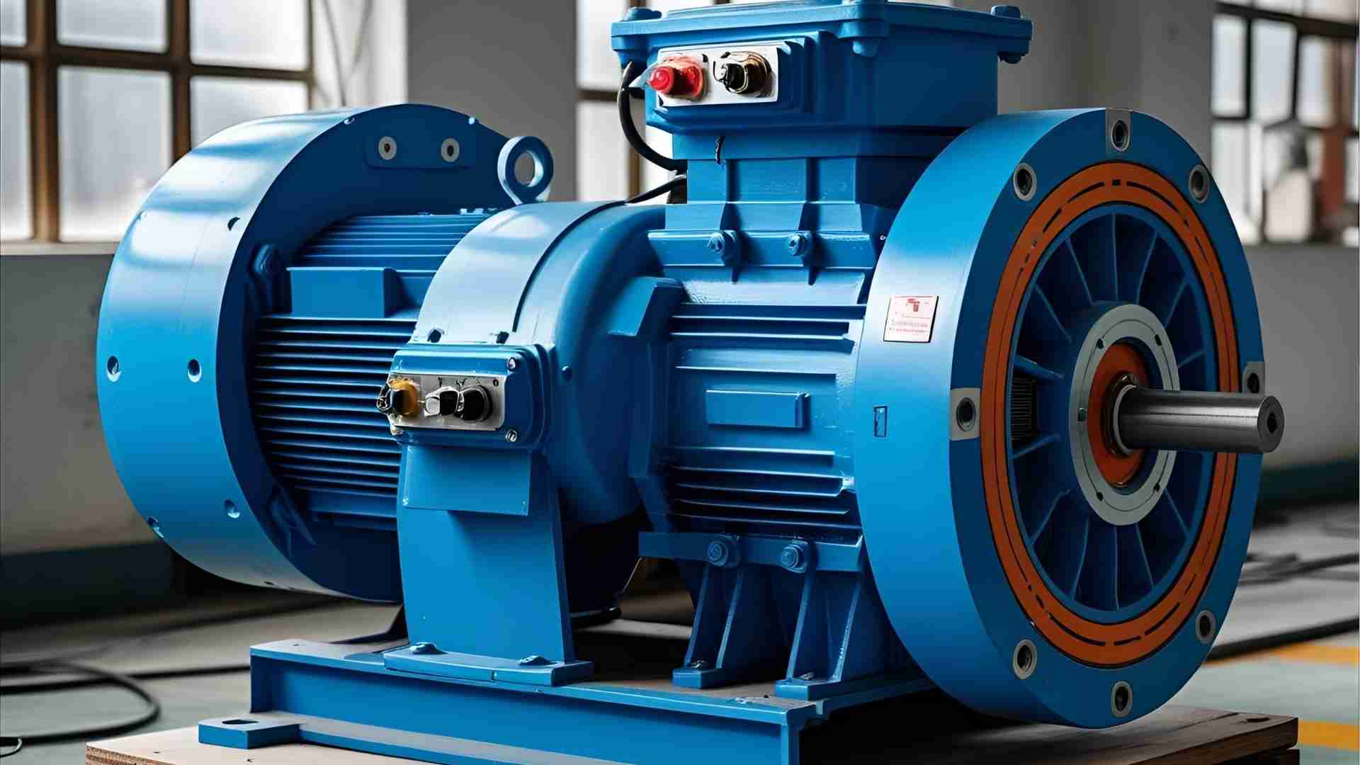
Explore the construction, working, and applications of 3-phase induction motors in marine systems, focusing on their efficiency and reliability.
Three-phase induction motors are the backbone of many industrial and marine applications due to their robustness, efficiency, and reliability. These motors are particularly vital in the maritime industry, where they power critical systems such as propulsion, pumps, compressors, and cargo-handling equipment. Their ability to operate efficiently in harsh marine environments makes them indispensable for seagoing vessels. This article delves into the construction, working principles, applications, advantages, challenges, and protective measures of 3-phase induction motors, with a focus on their significance in marine operations.
What is a 3-Phase Induction Motor?
A 3-phase induction motor, also known as an asynchronous motor, is an AC electric motor that operates using a three-phase power supply. The motor generates torque through electromagnetic induction, where a rotating magnetic field in the stator induces current in the rotor, causing it to rotate and produce mechanical power. Unlike single-phase induction motors, which require auxiliary starting mechanisms, 3-phase induction motors are self-starting, making them ideal for heavy-duty applications.
Types of 3-Phase Induction Motors
There are two primary types of 3-phase induction motors used in marine applications:
- Squirrel Cage Motor:
- Design: Features a rotor with short-circuited conductor bars arranged in a cage-like structure.
- Advantages: Simple, rugged, low-maintenance, and cost-effective.
- Applications: Widely used in lifts, cranes, large exhaust fans, auxiliary pumps, and heavy-load pumps (e.g., ballast, fire, freshwater, and seawater pumps).
- Wound Rotor (Slip Ring) Motor:
- Design: Contains rotor windings connected to external resistors via slip rings, allowing for variable speed control and high starting torque.
- Advantages: Suitable for applications requiring precise speed control or high starting torque.
- Applications: Used in systems like propulsion drives and heavy machinery requiring controlled startup.
Construction of 3-Phase Induction Motors
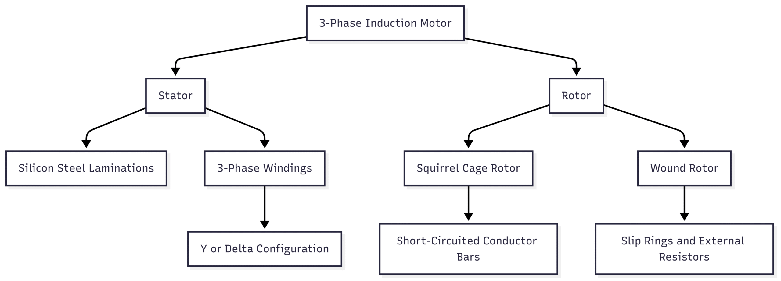
The construction of a 3-phase induction motor consists of two primary components: the stator and the rotor. These components work together to convert electrical energy into mechanical power.
Stator
- Structure: The stator is the stationary part of the motor, made of stacked silicon steel laminations to reduce eddy current losses. It contains slots that house three-phase windings.
- Windings: The windings are arranged in a Y (star) or delta configuration and connected to a 3-phase AC supply. They are wound for a specific number of poles, which determines the motor’s synchronous speed.
- Function: When energized, the stator windings produce a rotating magnetic field, which is essential for motor operation.
- Synchronous Speed Formula: The synchronous speed ((N_s)) of the motor is given by: [ N_s = \frac{120f}{p} ] where:
- (N_s) = Synchronous speed (in RPM)
- (f) = Frequency of the AC supply (in Hz)
- (p) = Number of poles
For example, a 6-pole motor operating at 60 Hz has a synchronous speed of: [ N_s = \frac{120 \times 60}{6} = 1200 , \text{RPM} ]
Rotor
- Structure: The rotor is the rotating component, consisting of a cylindrical laminated core with parallel slots. It is typically made of cast iron or aluminum.
- Conductor Bars: Heavy copper or aluminum bars are placed in the rotor slots and short-circuited at both ends by end rings in squirrel cage rotors. In wound rotors, windings are connected to slip rings.
- Skewed Slots: Rotor slots are slightly skewed to reduce magnetic hum, minimize noise, and prevent motor stalling.
- Function: The rotor rotates due to the interaction between the stator’s rotating magnetic field and the induced current in the rotor conductors.
Diagram: Motor Construction

Working Principle of 3-Phase Induction Motors
The operation of a 3-phase induction motor is based on electromagnetic induction and the interaction of magnetic fields.
- Power Supply and Magnetic Field:
- When a 3-phase AC supply is connected to the stator windings, it generates a rotating magnetic field. The field rotates at the synchronous speed, determined by the supply frequency and the number of poles.
- The sequence of the three-phase currents (R, Y, B) causes the magnetic flux to rotate around the stator core.
- Induction in the Rotor:
- According to Faraday’s Law of Electromagnetic Induction, the rotating magnetic field induces an electromotive force (EMF) in the rotor conductors.
- Since the rotor conductors are short-circuited (in squirrel cage motors) or connected to external resistors (in wound rotor motors), the induced EMF causes current to flow in the rotor.
- Torque Production:
- The rotor currents produce their own magnetic field, which interacts with the stator’s rotating magnetic field to generate torque.
- According to Lenz’s Law, the rotor rotates in the same direction as the magnetic field to reduce the relative velocity between the field and the rotor conductors.
- Slip and Rotor Speed:
- The rotor never reaches the synchronous speed because no EMF would be induced if the rotor and magnetic field were stationary relative to each other.
- The difference between the synchronous speed and the actual rotor speed is called slip, expressed as a percentage: [ \text{Slip} (%) = \frac{N_s – N_r}{N_s} \times 100 ] where (N_r) is the rotor speed.
- For example, a 6-pole motor at 60 Hz with a 5% slip has a rotor speed of: [ N_r = 1200 \times (1 – 0.05) = 1140 , \text{RPM} ]
- Load and Speed Regulation:
- As the load on the motor increases, the rotor slows slightly, increasing the slip. This allows more current to flow in the rotor, producing the necessary torque to meet the load demand.
- The speed variation between no-load and full-load conditions is minimal (1–5%), making 3-phase induction motors nearly constant-speed machines.
Applications in Marine Environments
Three-phase induction motors are integral to various shipboard systems due to their reliability and efficiency. Key applications include:
- Propulsion Systems:
- Used in diesel-electric propulsion systems to drive propellers, especially in Azipod systems found on cruise ships and icebreakers. Azipod systems integrate motors into steerable pods, enhancing maneuverability.
- Example: GE’s Advanced Induction Motor (AIM) is designed for naval propulsion, offering high torque and dual-speed operation.
- Pumps and Compressors:
- Power pumps for ballast systems, fire suppression, freshwater, and seawater circulation.
- Drive compressors for pneumatic controls and HVAC systems.
- Cargo Handling Equipment:
- Operate cranes, winches, and windlasses for loading and unloading cargo.
- Ensure precise and efficient cargo handling during port operations.
- Steering and Thrusters:
- Drive steering gear and side thrusters for precise vessel maneuvering.
- Essential for dynamic positioning in offshore vessels.
- Auxiliary Systems:
- Power large exhaust fans, engine room blowers, and auxiliary pumps for engine cooling and lubrication.
Table: Marine Applications of 3-Phase Induction Motors
| Application | Motor Type | Key Features |
|---|---|---|
| Propulsion | Squirrel Cage/Wound | High torque, reliable, efficient |
| Pumps | Squirrel Cage | Robust, low maintenance, suitable for heavy loads |
| Compressors | Squirrel Cage | Efficient air pressure regulation |
| Cargo Handling | Squirrel Cage/Wound | Precise control, high durability |
| Steering/Thrusters | Squirrel Cage | High reliability, precise maneuverability |
Advantages of 3-Phase Induction Motors
The design and operational characteristics of 3-phase induction motors offer several benefits, particularly in marine environments:
- Robustness and Simplicity: Their rugged construction with minimal moving parts ensures durability in harsh conditions.
- Self-Starting: No external starting devices are required, unlike single-phase or synchronous motors.
- Low Maintenance: The absence ofруса
- Efficiency: High energy conversion efficiency, reducing operational costs.
- Safety: Lack of sparking components (e.g., brushes) makes them suitable for hazardous environments like fuel-laden ship areas.
- Cost-Effectiveness: Relatively inexpensive compared to DC or synchronous motors.
- High Output: Produces approximately 1.5 times the power of a single-phase motor of the same size.
Challenges and Disadvantages
Despite their advantages, 3-phase induction motors face challenges in marine environments:
- High Starting Current:
- Draws significant current during startup, causing voltage dips. Soft starters or star-delta starters mitigate this issue.
- Lagging Power Factor:
- Operates at a lagging power factor, leading to increased losses at low loads. Static capacitor banks can improve the power factor.
- Speed Control Difficulty:
- Speed control is complex compared to DC motors. Variable frequency drives (VFDs) are used for precise speed regulation.
- Environmental Challenges:
- High moisture, temperature variations, and vibrations from ship machinery can affect performance.
- Corrosion due to seawater exposure can damage bearings, shafts, and windings.
- Electrical Faults:
- Issues like single phasing, unbalanced voltage, or short circuits can disrupt operations.
- Single phasing occurs when one or more phases are lost, causing overheating and reduced efficiency.
- Mechanical Faults:
- Rotor imbalance, bearing failure, fatigue, and lubrication issues can reduce motor lifespan.
- Improper maintenance or poor-quality parts exacerbate these problems.
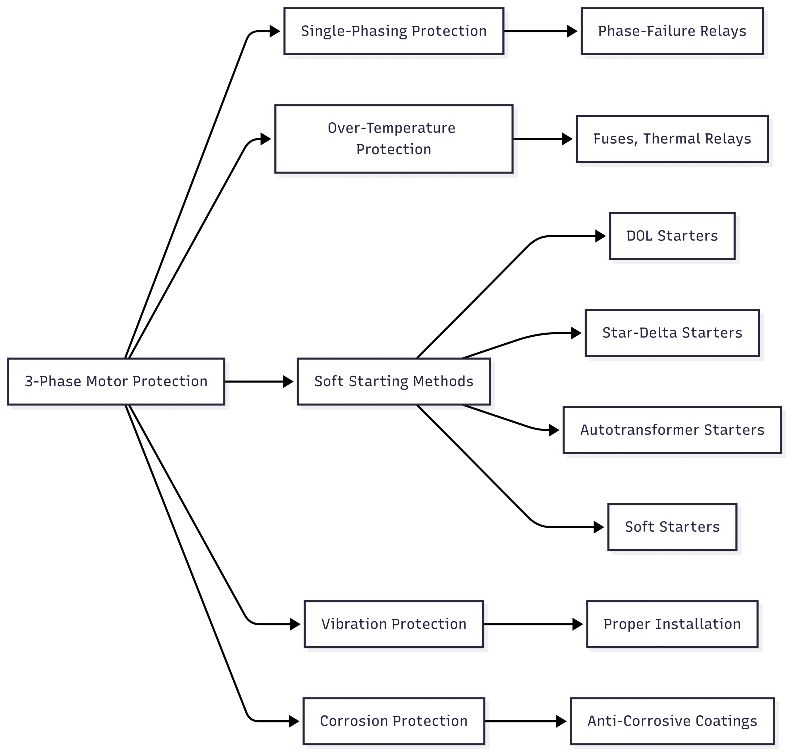
Protective Measures for 3-Phase Induction Motors
To ensure reliable operation and longevity, several protective measures are implemented:
- Single-Phasing Protection:
- Motors above 500 kW are equipped with protection devices to prevent damage from single-phasing, such as phase-failure relays.
- Over-Temperature Protection:
- Fuses, thermal relays, and temperature sensors protect against overheating due to overloading or electrical faults.
- Soft Starting Methods:
- Direct Online (DOL) Starters: Simple but suitable for small motors due to high starting current.
- Star-Delta Starters: Reduce starting current by initially connecting windings in a star configuration, then switching to delta.
- Autotransformer Starters: Lower voltage during startup to reduce current draw.
- Soft Starters: Gradually increase voltage to minimize mechanical and electrical stress.
- Vibration and Corrosion Protection:
- Proper installation and regular maintenance prevent vibration-induced damage.
- Anti-corrosive coatings and sealed enclosures protect against moisture and seawater corrosion.
- Lubrication Management:
- Regular lubrication with high-quality grease prevents bearing wear and friction-related failures.
Diagram: Protective Measures

Specifications and Pricing
Typical Specifications
| Specification | Squirrel Cage Motor | Wound Rotor Motor |
|---|---|---|
| Power Range | 0.5 kW–5000 kW | 5 kW–10,000 kW |
| Voltage | 400V, 690V, 3.3kV, 6.6kV | 400V, 690V, 3.3kV, 6.6kV |
| Frequency | 50 Hz or 60 Hz | 50 Hz or 60 Hz |
| Poles | 2, 4, 6, 8, or more | 4, 6, 8, or more |
| Efficiency | 85–95% | 80–90% |
| Protection Class | IP55 (dust and water-resistant) | IP44–IP55 |
| Cooling Method | TEFC (Totally Enclosed Fan-Cooled) | TEFC |
| Weight | 10–5000 kg (varies by size) | 50–10,000 kg (varies) |
Pricing
The cost of 3-phase induction motors varies based on power rating, type, and marine-specific certifications (e.g., ABS, DNV, Lloyd’s Register). Approximate price ranges for marine-grade motors:
- Squirrel Cage Motors:
- Small (0.5–10 kW): $500–$2,000
- Medium (10–100 kW): $2,000–$10,000
- Large (100–1000 kW): $10,000–$50,000
- Wound Rotor Motors:
- Medium (10–100 kW): $5,000–$20,000
- Large (100–1000 kW): $20,000–$100,000
- Specialized Motors (e.g., Azipod, GE AIM):
- Prices can exceed $100,000 due to custom designs and certifications.
Maintenance and Operational Best Practices
To maximize the lifespan and efficiency of 3-phase induction motors in marine environments:
- Regular Inspections:
- Check for signs of corrosion, vibration, or overheating.
- Inspect windings for insulation degradation.
- Lubrication:
- Use marine-grade grease and follow manufacturer-recommended lubrication schedules.
- Monitor for contamination in lubricants.
- Alignment and Installation:
- Ensure proper alignment with the load to prevent rotor imbalance.
- Secure the motor to a stable foundation to minimize vibrations.
- Electrical Monitoring:
- Use protection devices to monitor voltage, current, and phase balance.
- Install VFDs for applications requiring variable speed.
- Environmental Protection:
- Use IP55-rated enclosures for protection against water and dust.
- Apply anti-corrosive coatings to motor components.
Conclusion
Three-phase induction motors are critical to the maritime industry, powering essential systems like propulsion, pumps, compressors, and cargo-handling equipment. Their robust construction, self-starting capability, and high efficiency make them ideal for the harsh marine environment. Despite challenges like high starting currents, lagging power factors, and environmental wear, protective measures such as soft starters, single-phasing protection, and proper maintenance ensure reliable performance. With their versatility and cost-effectiveness, these motors remain the preferred choice for marine applications, driving vessels efficiently across the seas.
Happy Boating!
Share 3 Phase Induction Motor – Construction and Working with your friends and leave a comment below with your thoughts.
Read What is a marine diesel engine overhaul? until we meet in the next article.
