10 Important Tests for Major Overhauling of Ship’s Generator
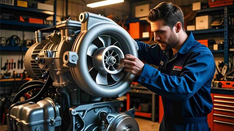
Major overhauling, commonly known as D’carb, is a critical maintenance procedure for ship’s generators. These diesel-driven alternators serve as the primary power source on board, supplying electricity for propulsion auxiliaries, navigation, and life-support systems. Failure during operation can lead to blackouts, machinery damage, or safety incidents.
The overhaul restores the engine and alternator to manufacturer specifications through disassembly, inspection, repair, and reassembly. Comprehensive testing of tools, components, and systems before, during, and after the process is mandatory to verify tolerances, detect hidden defects, and confirm functionality.
The 10 tests detailed here focus on high-stress mechanical parts, combustion components, starting systems, and electrical safeties. They address common failure modes such as fatigue cracks from reversal loads, pressure leaks, misalignment, and insulation breakdown. Additional key checks—bearing clearances, alternator air gap, and crankcase inspection—complement these tests. All procedures follow manufacturer manuals and classification society guidelines. Proper execution minimizes downtime and extends service life.
Key Aspects of the Overhaul Process
Bearing Clearances: Crankpin and main bearing clearances must stay within manufacturer limits to prevent metal-to-metal contact or excessive oil film thinning. Use plastigauge or micrometers for measurement during reassembly. Typical values range from 0.10–0.25 mm for main bearings and 0.08–0.20 mm for crankpin bearings, depending on engine size. Out-of-spec clearances cause overheating, vibration, and premature failure.
Air Gap Measurement: For the alternator, measure the radial air gap between stator and rotor at multiple points with feeler gauges. Uniform gap (typically 1.5–3.0 mm) ensures balanced magnetic flux and prevents rotor-stator contact or vibration. Uneven gaps create unbalanced forces, leading to bearing wear and electrical inefficiency.
Crankcase Inspection: After cleaning, inspect the crankcase interior for sludge, carbon deposits, or white metal particles from bearing wear. Magnetic plugs and visual checks identify early issues. Any debris indicates lubrication problems that must be resolved before reassembly.
These foundational checks integrate with the 10 specific tests below, performed in a logical sequence during disassembly, component overhaul, reassembly, and final verification.
The 10 Important Tests
1. Hydraulic Jack Test/Calibration
Hydraulic jacks and pumps handle heavy loads when removing cylinder heads, main bearing caps, and connecting rod bolts. Faulty tools can apply uneven or excessive force, damaging components or causing personal injury.
Procedure: Before any disassembly, connect each jack and pump to a calibrated test rig. Pressurize to 1.5 times the working pressure (typically 200–400 bar depending on model) and hold for 5–10 minutes. Check for leaks at seals, hoses, and valves. Calibrate pressure gauges against a master gauge. Release pressure slowly and repeat the cycle three times. Record readings and tag tools as “tested and calibrated.”
Skipping this test risks bolt distortion or head warpage during opening. Always use manufacturer-recommended hydraulic fluid and replace damaged seals immediately.
2. Cylinder Head Pressure Test
Cylinder heads endure extreme combustion pressures and thermal cycling. Overhauled or reconditioned heads must be leak-free before reinstallation.
Procedure: Blank all ports except inlet and outlet. Fill with water or apply compressed air at 1.5–2 times the maximum combustion pressure (often 30–50 bar test pressure). Hold for 30 minutes while monitoring for pressure drop or visible leaks at valve seats, cracks, or cooling passages. Use dye in water for better visibility. Repair or replace any defective head.
This test detects micro-cracks and valve leakage that could cause compression loss, overheating, or coolant ingress into the combustion chamber.
3. Bearing Cap Crack Test
Bearing caps and housing serrations secure the crankshaft under high loads. Cracks here compromise alignment and can lead to catastrophic bearing failure.
Procedure: Clean surfaces thoroughly. Apply die penetrant (NDT) per kit instructions: penetrant dwell time 10–20 minutes, remove excess, apply developer, and inspect under UV or white light for linear indications. Pay special attention to serrations and bolt seating areas. Any crack requires cap replacement.
The serrated design transfers load between caps; undetected cracks propagate under reversal stresses.
4. Connecting Rod Bolt Crack Test
Connecting rod bolts experience severe tensile and bending stresses during every revolution. Fatigue cracks are a primary cause of engine seizures.
Procedure: Remove bolts, clean ultrasonically or with solvent. Perform die penetrant test on the entire shank, threads, and head. Inspect for transverse cracks, especially at stress concentration points. Replace any bolt showing indications—even minor ones. Torque new bolts strictly to specification with hydraulic tensioners.
This non-destructive test is mandatory at every major overhaul due to the high reversal loading.
5. Connecting Rod Bend Test
A bent connecting rod causes uneven bearing loading, accelerated wear, and piston side thrust.
Procedure: After removal, insert a precision brass rod (diameter 0.05–0.10 mm smaller than the oil bore) through the full length of the lubrication passage. The rod must slide freely without binding. If it does not pass, the rod is bent and requires replacement or specialist straightening. Measure overall length and parallelism with a micrometer for confirmation.
Visual inspection alone cannot detect slight bends that appear straight to the naked eye.
6. Fuel Injector Pressure Test
Fuel injectors control atomization and injection timing. Wear in nozzles and springs leads to dribbling, poor combustion, and carbon buildup.
Procedure: Mount each injector on a calibrated test bench. Pump test oil to check opening pressure (typically 250–350 bar), spray pattern (fine, even cone without streaks), and shut-off (no dribble after injection). Adjust shims if pressure is out of tolerance. Test for back-leakage and chatter. Clean or replace faulty injectors.
Only injectors passing all parameters return to service.
7. Starting Air Valve Leakage Test
Starting air valves admit compressed air for engine cranking. Internal leakage can cause slow starting, backfiring, or valve damage.
Procedure: After overhaul, install valves temporarily in the cylinder head or use a test fixture. Apply service air pressure (typically 25–30 bar) and monitor for leakage past the seat using soapy water or acoustic detection. No bubbles or audible leak is acceptable. Lap seats if minor leakage occurs; replace valve if persistent.
This test prevents compressed air from entering the combustion chamber during normal operation.
8. Relief Valve Pressure Test
Cylinder head relief valves protect against overpressure from fuel accumulation or misfiring.
Procedure: Mount the valve on a bench test rig with high-pressure air supply, control valve, and calibrated digital gauge. Increase pressure gradually until the valve lifts at the exact set point (usually 10–15% above maximum combustion pressure). Adjust spring tension if needed. Test blow-down and reseating. Record lift pressure and reseat pressure.
A malfunctioning relief valve risks head explosion or crankcase damage.
9. Current Test (Turning Gear Motor Monitoring)
After reassembly but before fuel introduction, this test verifies smooth mechanical rotation.
Procedure: Engage the turning gear with indicator cocks open. Start the electric turning gear motor and bar the engine through several revolutions while continuously monitoring motor current draw with a clamp meter. Normal current remains steady and low. Any sudden spike or fluctuation indicates binding, misalignment, or internal obstruction. Investigate and correct before proceeding.
This electrical signature reveals mechanical issues invisible during static inspection.
10. Alarm and Trip System Test
Safeties prevent operation under dangerous conditions. The alarm and trip circuits must function reliably.
Procedure: With the engine on turning gear, simulate conditions or use test signals: low lube oil pressure, high cooling water temperature, overspeed, and low fuel pressure. Verify that alarms activate at set points and trips shut down the engine. Check wiring, contacts, and sensors for continuity. Calibrate pressure and temperature switches. Test emergency stop pushbuttons.
All tests must pass before final handover.
Summary Table of Tests
| Test No. | Test Name | Purpose | Primary Method | Typical Acceptance Criteria |
|---|---|---|---|---|
| 1 | Hydraulic Jack Calibration | Safe disassembly torque | Pressure hold test on rig | No leaks at 1.5× working pressure |
| 2 | Cylinder Head Pressure Test | Detect cracks and valve leaks | Water/air pressurization | No pressure drop in 30 min |
| 3 | Bearing Cap Crack Test | Structural integrity | Die penetrant (NDT) | No linear indications |
| 4 | Con-Rod Bolt Crack Test | Fatigue resistance | Die penetrant (NDT) | No cracks on shank or threads |
| 5 | Connecting Rod Bend Test | Alignment verification | Brass rod through oil bore | Rod passes freely |
| 6 | Fuel Injector Pressure Test | Proper atomization | Test bench | Correct opening pressure, no dribble |
| 7 | Starting Air Valve Leak Test | Prevent backflow | Service air with soap test | Zero leakage |
| 8 | Relief Valve Pressure Test | Overpressure protection | Bench rig with gauge | Lifts at exact set pressure |
| 9 | Current Test | Mechanical smoothness | Turning gear motor current | Steady current draw, no spikes |
| 10 | Alarm and Trip System Test | Safety functionality | Simulation of fault conditions | All alarms and trips activate correctly |
Additional Electrical Integrity Check: Insulation Resistance (Megger) Test
Although not always numbered among the mechanical tests, the megger test on stator and rotor windings is essential before commissioning. Use a 500 V or 1000 V insulation tester. Minimum acceptable resistance is 1 MΩ (phase to ground and phase to phase) at 40 °C, corrected for temperature. Low readings indicate moisture or insulation damage requiring drying or rewinding.
Overhaul Process Flowchart
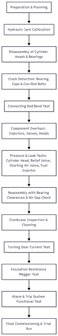
Following these 10 tests plus supporting checks guarantees the generator returns to service with restored performance, reduced vibration, optimal fuel efficiency, and full safety compliance. Marine engineers must document every result, retain test records for surveys, and use only OEM-approved spares. Systematic execution of these procedures prevents unplanned outages and protects the vessel’s operational readiness.
Happy Boating!
Share 10 Important Tests for Major Overhauling of Ship’s Generator with your friends and leave a comment below with your thoughts.
Read What is Volatile Organic Compound (VOC)? until we meet in the next article.